AN0034 Getting started with PSOC™ 4 HV MS MCUs in ModusToolbox™
About this document
Scope and purpose
This application note helps you explore the PSOC™ 4 high voltage (HV) mixed signal (MS) Automotive MCU architecture and development tools, and shows you how to create your first project using the Eclipse IDE for ModusToolbox™ software. This application note also guides you to more resources available online to accelerate your learning about PSOC™ 4 HV MS: CY8C41x5 and CY8C41x6 MCUs.
Intended audience
This document is intended for users who are new to PSOC™ 4 HV MS MCU and ModusToolbox™ software.
Associated part family
CY8C41x5
CY8C41x6
Software version
3.2 or above.
Introduction
The PSOC™ 4 HV MS MCU device is a microcontroller targeted at automotive applications. The PSOC™ 4 HV MS CY8C41x MCU integrates the following features on a single chip:
CPU subsystem
48 MHz, 32-bit Arm® Cortex®-M0+ CPU with the following:
Single-cycle multiply
Memory protection unit (MPU)
Datawire/peripheral direct memory access (DMA) controller with 8 channels
Integrated memories
Up to 64 KB of flash
Up to 8 KB of SRAM
Programmable analog
12-bit, 1-Msps SAR ADC with differential and single-ended modes, and channel sequencer with signal averaging
16-channel SAR multiplexer with built-in diagnostics (8 I/O channels and 8 diagnostic channels)
Temperature sensor built into SAR ADC
Two low-power comparators that operate in Deep Sleep low-power mode
Programmable digital
Programmable smart I/O logic blocks allowing Boolean operations to be performed on port inputs and outputs
High-voltage subsystem
Regulator output voltage supports 3.3 V or 5 V selectable with ±2% trimmed accuracy
Regulator current: up to 60 mA
Thermal shutdown
Operates directly off 12-V/24-V battery (tolerates up to 42 V)
CAPSENSE™ (multi-sense converter) block
Multi-sense converter (MSC) provides a best-in-class signal-to-noise ratio (SNR) (>5:1) and water tolerance for capacitive sensing
Timing and pulse-width modulation
Five 16-bit timer/counter/pulse-width modulator (TCPWM) blocks
Communication
Two independent run-time reconfigurable serial communication blocks (SCB) with reconfigurable I 2 C, SPI, UART, or LIN slave functionality
Up to two CXPI channels with data rate up to 20 kbps
The
ModusToolbox™ software environment
supports PSOC™ 4 HV MS MCU application development with a set of tools for configuring the device, setting up the peripherals, and complementing your projects with world-class middleware. See the
Infineon
GitHub repo for the KIT_PSOC4-HVMS-64K_LITE BSP, libraries for popular functionality like device firmware upgrade (DFU) and emWin, and a comprehensive array of example applications to get you started.
illustrates an application-level block diagram for a Steering wheel hands-on-detection (HOD) use case using a PSOC™ 4 HV MS MCU.
Figure 1. Application-level block diagram using PSOC™ 4 HV MS MCU
The PSOC™ 4 HV MS MCU is a highly capable and flexible solution. For example, the steering wheel hands-on-detection use case in
Figure 1
has the advantage of the following features:
MCU:
Arm® Cortex®-M0+ MCU with DMA and MPU
Up to 64 KB flash with error correcting code (ECC)
CAPSENSE™:
Handles high parasitic capacitance (Cp) to support long sensors
Temperature compensation along with heated steering wheels
Supports thick overlay/steering wheel covers
Heating coil can be used as an HOD sensor
ADC:
Monitors supply voltage
Measures temperature of the sensor
PWM:
Controls haptic actuator
Controls LED lighting
HV (LDO and LIN PHY):
Connects directly to a 12-V battery supply with the integrated HV regulator
Communicates directly to the LIN bus with an integrated LIN PHY
provides an overview of the product line.
Device series | Details |
|---|---|
PSOC™ 4 HV MS CY8C4125 | 24 MHz Cortex®-M0+ 32 KB flash, 4 KB RAM Packages: 32/48/56 QFN |
PSOC™ 4 HV MS CY8C4126 | 24 MHz Cortex®-M0+ 64 KB flash, 8 KB RAM Packages: 32/48/56 QFN |
PSOC™ 4 HV MS CY8C4145 | 48 MHz Cortex®-M0+ 32 KB flash, 4 KB RAM Packages: 32/48/56 QFN |
PSOC™ 4 HV MS CY8C4146 | 48 MHz Cortex®-M0+ 64 KB flash, 8 KB RAM Packages: 32/48/56 QFN |
Note: All features are not available in all the devices in a product line. For more details, see the Device datasheets.
This application note introduces you to the capabilities of the PSOC™ 4 HV MS MCU, gives an overview of the development ecosystem, and gets you started with a simple “Hello World” application wherein you learn to use the PSOC™ 4 HV MS MCU. Additionally, provides how to create the application from an empty starter application, but the completed design is available as a
code example for ModusToolbox™ on GitHub
.
For hardware design considerations, see the
2
.
Development ecosystem
PSOC™ 4 HV MS MCU resources
The
32-bit PSOC™ 4 HV Arm® Cortex® microcontroller
webpage contains wealth of data that will assist you in selecting the right PSOC™ 4 HV MS device and quickly and effectively integrate it into your design. For a comprehensive list of PSOC™ 4 HV MS MCU resources, see
How to design with PSOC™ 4 HV MS MCU
. The following is an abbreviated list of resources for the PSOC™ 4 HV MS MCUs.
- Overview: PSOC™ 4 HV MCU webpage
Product selectors: PSOC™ 4 HV MS CY8C41x5/CY8C41x6 series MCU
Datasheets describe and provide electrical specifications for each device family
Application notes and code examples cover a broad range of topics, from basic to advanced
Reference manuals provide detailed descriptions of the architecture and registers in each device family
PSOC™ 4 HV MS MCU programming specification: Provides the information necessary to program the nonvolatile memory of PSOC™ 4 HV MS MCU devices
Development tools: KIT_PSOC4-HVMS-64K_LITE
- Technical support: PSOC™ 4 Developer Community forum, knowledge base articles
Firmware/application development
For application development with the PSOC™ 4 HV MS MCUs, use the ModusToolbox™ development platform. ModusToolbox™ includes configuration tools, low-level drivers, middleware libraries, operating system support, and other packages for creating MCU.
Choosing an IDE
ModusToolbox™, the latest-generation toolset, includes the Eclipse IDE and therefore, supports across Windows, Linux, and macOS platforms. The Eclipse IDE for ModusToolbox™ is integrated with quick launchers for tools and design configurators in the Quick Panel. Third-party IDEs supported by ModusToolbox™ include Visual Studio Code, Arm® MDK (µVision), and IAR Embedded Workbench. The associated hardware and middleware configurators also work on all three host operating systems.
Use ModusToolbox™ to take advantage of the power and extensibility of an Eclipse-based IDE.
ModusToolbox™ software
ModusToolbox™ is a collection of tools and software that provides an immersive development experience for creating converged MCUs and allows you to integrate our devices into your existing development methodology. To achieve this goal, ModusToolbox™ leverages popular third-party ecosystems, such as FreeRTOS and Arm® Mbed OS, and adds specific features for security.
Eclipse IDE for ModusToolbox™ is a multi-platform development environment that supports application configuration and development.
shows a high-level view of the tools/resources included in the ModusToolbox™ software. For a more in-depth overview of the ModusToolbox™ software, see the
ModusToolbox™ user guide
.
Figure 2. ModusToolbox™ software
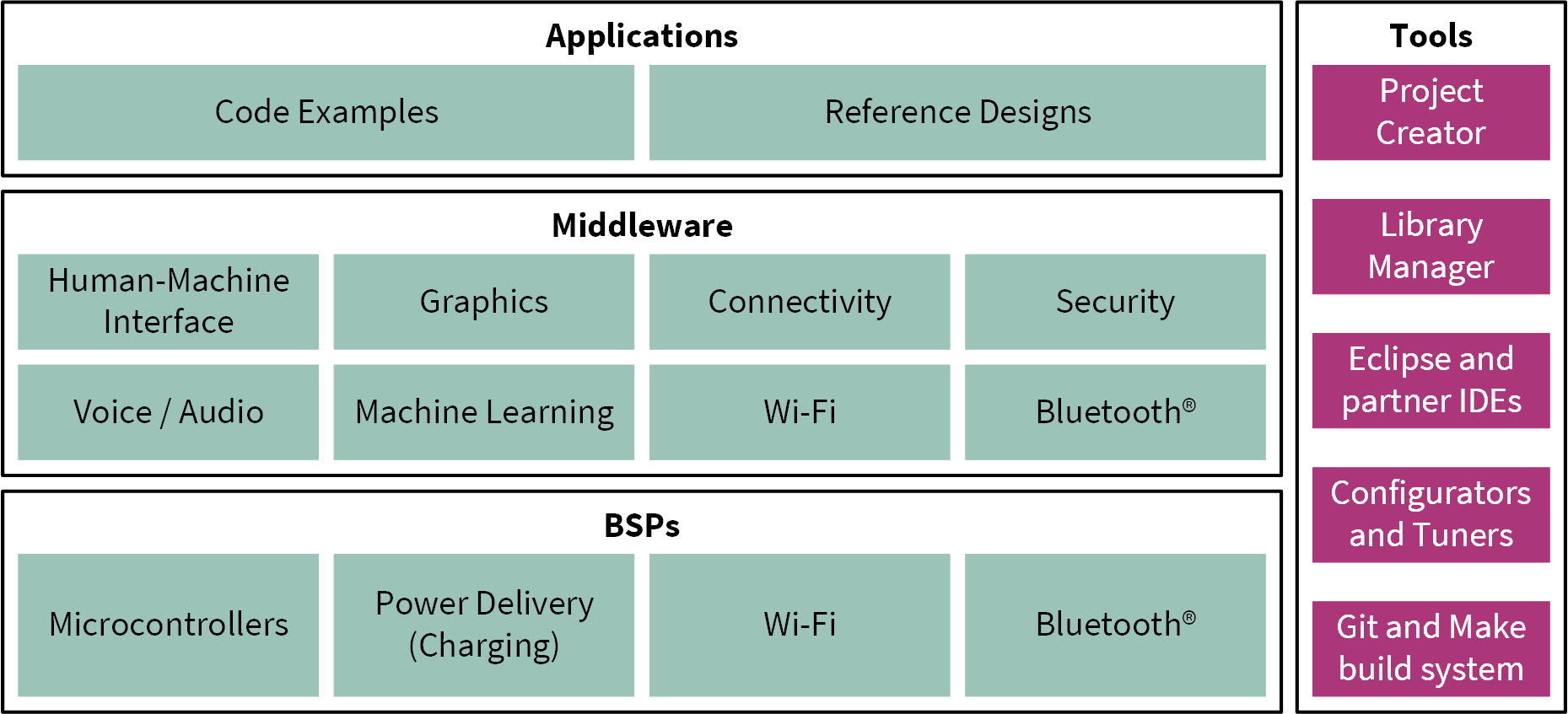
The ModusToolbox™ installer includes the design configurators and tools, and the build system infrastructure.
The build system infrastructure includes the new project creation wizard that can be run independent of the Eclipse IDE, the make infrastructure, and other tools.
All the ModusToolbox™ development flows depend on the provided low-level resources. These include:
Board support packages (BSP) – A BSP is the layer of firmware containing board-specific drivers and other functions. The board support package is a set of libraries that provide APIs to initialize the board and provide access to board level peripherals. It includes low-level resources such as Peripheral Driver Library (PDL) for board peripherals. It uses the HAL to configure the board. Custom BSPs can be created to enable support for end-application boards. See the “Board Support Packages” section in the ModusToolbox™ user guide for more information
Hardware Abstraction Layer (HAL)
– HAL provides a high-level interface to configure and use hardware blocks on MCUs. It is a generic interface that can be used across multiple product families. The focus on ease-of-use and portability means that the HAL does not expose all the low-level peripheral functionality. The HAL wraps the lower-level drivers (such as PSOC™ 4 HV MS PDL) and provides a high-level interface to the MCU. The interface is abstracted to work on any MCU. This helps you write application firmware independent of the target MCU
The HAL can be combined with platform-specific libraries (such as PSOC™ 4 HV MS PDL) within a single application. You can leverage the HAL's simpler and more generic interface for most of an application, even if one portion requires finer-grained control
Peripheral Driver Library (PDL)
– The PDL integrates the device header files, startup code, and peripheral drivers into a single package. The PDL supports the PSOC™ 4 HV MS MCU device family. The drivers abstract the hardware functions into a set of easy-to-use APIs. These are fully documented in the PDL API Reference manual
The PDL reduces the need to understand register usage and bit structures, therefore, easing software development for the extensive set of peripherals in the PSOC™ 4 HV MS MCU series. You configure the driver for your application, and then use API calls to initialize and use the peripheral
Extensive middleware libraries that provides specific capabilities to an application. All the middleware is delivered as libraries and via GitHub repositories
PSOC™ 4 HV MS MCU software resources
The PSOC™ 4 HV MS MCU software includes driver and middleware configurators to get you started developing firmware with PSOC™ 4 HV MS MCU. It contains configurators, drivers, libraries, middleware, various utilities, Makefiles, and scripts. It also includes relevant drivers, middleware, and examples for use with industrial applications. You may use any or all tools in any environment you prefer.
Configurators
ModusToolbox™ software provides graphical applications called configurators that make it easier to configure a hardware block. For example, instead of having to search through all the documentation to configure a Serial Communication Block (SCB) as a UART with a desired configuration, open the appropriate configurator and set the baud rate, parity, and stop bits. After saving the hardware configuration, the tool generates the C code to initialize the hardware with the desired configuration.
Configurators are independent of each other, but they can be used together to provide flexible configuration options. They can be used standalone, in conjunction with other tools, or within a complete IDE. Configurators are used for:
Setting options and generating code to configure drivers
Setting up connections such as pins and clocks for a peripheral
Setting options and generating code to configure middleware
The following configurators are available for PSOC™ 4 HV MS MCU applications:
Device Configurator: Sets up the system (platform) functions and the basic peripherals (for example, UART, Timer, and PWM)
CAPSENSE™ Configurator: Configures CAPSENSE™ widgets and generates code to control the application firmware
CAPSENSE™ Tuner Tune CAPSENSE™ applications
Smart I/O Configurator: Configures the smart I/O
Each of these configurators creates their own files (e.g.,
design.cyqspi
for QSPI). The configurator files ( design.modus or
design.cyqspi
) are usually provided with the BSP. The files are copied into the application when an application is created based on a BSP. Additionally, you can create custom device configurator files for an application and override the BSP-provided devices.
Library management for PSOC™ 4 HV MS MCU
With the release of ModusToolbox™ v3.2, applications can optionally share board support packages (BSPs) and libraries. If needed, different applications can use different versions of the same BSP or library. The file types associated with libraries using this flow have a
.mtb
extension.
Section
My first PSOC™ 4 HV MS MCU design using Eclipse IDE for ModusToolbox™ software
of this document describes creating a new application using this flow.
For more information on ModusToolbox™ flow, see the
Library Manager user guide
located at
<install_dir>/ModusToolbox/tools_<version>/library-manager/docs/library-manager.pdf
.
Software development for PSOC™ 4 HV MS MCU
Significant source code and tools are provided to enable software development for PSOC™ 4 HV MS MCUs. You use tools to specify how you want to configure the hardware, generate code for that purpose which you use in your firmware, and include various middleware libraries for additional functionality, like FreeRTOS. This source code makes it easier to develop the firmware for supported devices. It helps you quickly customize and build firmware without the need to understand the register set.
In the ModusToolbox™ environment, you use configurators to configure either the device or a middleware library, such as QSPI functionality.
The PSOC™ 4 HV MS MCU Peripheral Driver Library code is delivered as the
mtb-pdl-cat2
library. Middleware is delivered as separate libraries for each feature/function.
Whether you use the Eclipse IDE, a third-party IDE, or the command-line, firmware developers who wish to work at the register level should see the driver source code from the PDL. The PDL includes all the device-specific header files and startup code you need for your project. It also serves as a reference for each driver. Because the PDL is provided as source code, you can see how it accesses the hardware at the register level.
Some devices do not support particular peripherals. The PDL is a superset of all the drivers for any supported device. This superset design means:
All API elements needed to initialize, configure, and use a peripheral are available
The PDL is useful across various PSOC™ 4 HV MS MCU devices, regardless of available peripherals
The PDL includes error checking to ensure that the targeted peripheral is present on the selected device
This enables the code to maintain compatibility across products of the PSOC™ 4 HV MS MCU family as long as the peripherals are available. A device header file specifies the peripherals that are available for a device. If you write the code that attempts to use an unsupported peripheral, you will get an error at compile time. Check the datasheet for the specific device to ensure that the peripheral is supported before writing the code to use that peripheral.
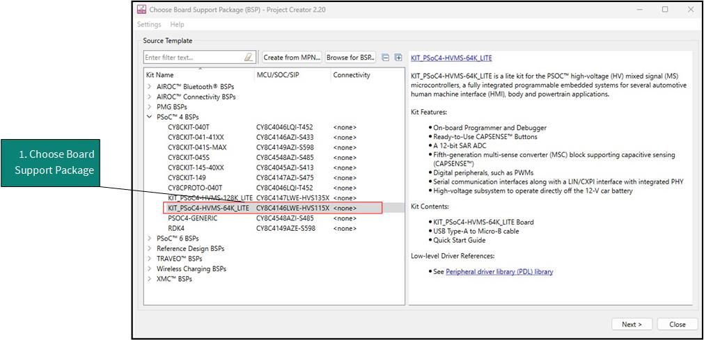
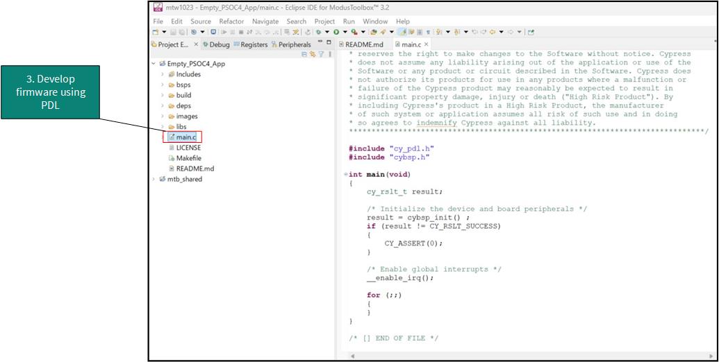
As shown in
Figure 3
, with the Eclipse IDE for ModusToolbox™ software, you can:
Choose a board support package (BSP)
Create a new application based on a list of starter applications, filtered by kit
Develop your application firmware using the PDL for PSOC™ 4 HV MS MCU
Figure 3. Eclipse IDE for ModusToolbox™ resources
Support for other IDEs
You can develop firmware for PSOC™ 4 HV MS MCUs using your favorite IDE such as
IAR Embedded Workbench
or
Visual Studio Code
.
ModusToolbox™ configurators are standalone tools that can be used to set up and configure PSOC™ 4 HV MS MCU resources and other middleware components without using the Eclipse IDE. The Device Configurator and middleware configurator use the
design.x
files within the application workspace. You can then point to the generated source code and continue developing firmware in your IDE.
If there is a change in the device configuration, edit the
design.x
files using the configurators and regenerate the code for the target IDE. It is recommended that you generate resource configurations using the configuration tools provided with ModusToolbox™ software.
FreeRTOS support with ModusToolbox™
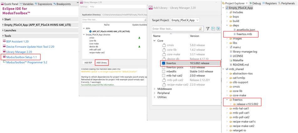
Adding native FreeRTOS support to a ModusToolbox™ application project is like adding any library or middleware. You can import the FreeRTOS middleware into your application by using the Library Manager. Select the application project and click the
Library Manager
link in the
Quick Panel
. Select
freertos
from the Libraries > PSOC™ 4 HV MS MCU Middleware dialog, as shown in
Figure 4
.
The
.mtb
file pointing to the FreeRTOS middleware is added to the application project. The middleware content is also downloaded and placed inside the corresponding folder called freertos. To continue working with FreeRTOS, follow the steps in the Quick Start section of
FreeRTOS documentation
.
Figure 4. Import FreeRTOS middleware in ModusToolbox™ application
Programming/debugging
All PSOC™ 4 HV MS MCU kits have a KitProg3 onboard programmer or debugger. It supports Cortex® microcontroller Software Interface Standard - Debug Access Port (CMSIS-DAP). See the
KitProg3 user guide
for details.
The Eclipse IDE requires KitProg3 and uses the
OpenOCD
protocol for debugging PSOC™ 4 HV MS MCU applications. Additionally, it supports GDB debugging using industry-standard probes like the
Segger J-Link
.
ModusToolbox™ includes the
fw-loader
command-line tool to update and switch the KitProg firmware from KitProg2 to KitProg3.
For more details, see the “Program and debug” section in the
Eclipse IDE for ModusToolbox™ user guide
.
PSOC™ 4 HV MS MCU development kits
- Development kits
PSOC™ 4 HV MS 64K Lite Kit ( PSOC4_HVMS_LITE_KIT )
Device features
CY8C41x6
Figure 5. PSOC™ 4 HVMS-64K MCU block diagram
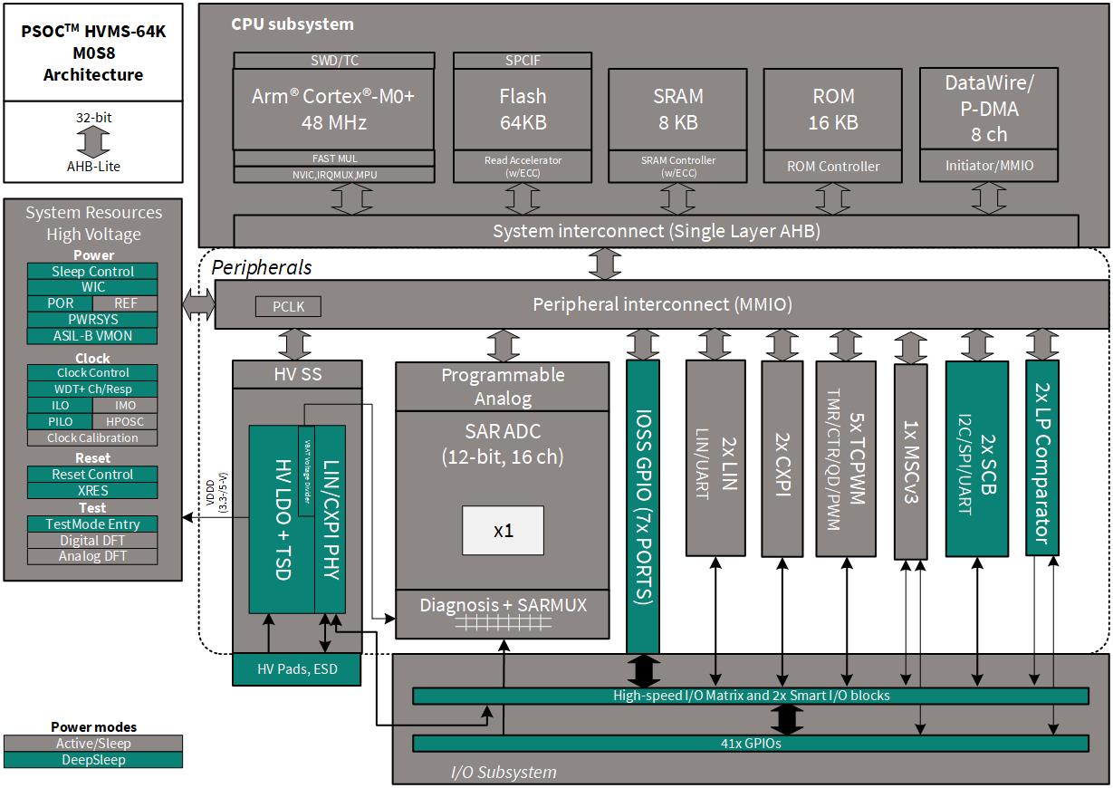
- CPU subsystem
48 MHz Arm® Cortex®-M0+ CPU
Three DMA controllers
- Integrated memories
Up to 64 KB of code flash
Up to 8 KB of SRAM
- Programmable analog
12-bit, 1-Msps SAR ADC with differential and single-ended modes, and channel sequencer with signal averaging
16-channel SAR multiplexer with in-built diagnostics (8 I/O channels and 8 diagnostic channels)
Temperature sensor built into SAR ADC
Two low-power comparators that operate in Deep Sleep low-power mode
- Programmable digital
Programmable smart I/O logic blocks allowing Boolean operations to be performed on port inputs and outputs
- High-voltage subsystem
Regulator output voltage supports 3.3 V or 5 V selectable with ±2% trimmed accuracy
Regulator current: up to 60 mA
Thermal shutdown
Operates directly off 12-V/24-V battery (tolerates up to 42 V)
Integrated local interconnect network (LIN)/clock extension peripheral interface (CXPI) transceiver
- CAPSENSE™ (multi-sense converter) block
Multi-sense converter (MSC) provides a best-in-class signal-to-noise ratio (SNR) (>5:1) and water tolerance for capacitive sensing
One MSC converter supported
Autonomous channel scanning without CPU assistance
- Functional safety for ASIL-B
The device will be developed according to the development process of ISO 26262 for ASIL-B as a Safety Element out of Context (SEooC) (according to ISO 26262-10:2018E, clause 9)
Memory protection unit (MPU)
Window watchdog timer (WDT) with challenge-response functionality
Supply monitoring; detection of overvoltage and brownout events for 3.3 V or 5 V, and 1.8 V supplies
Hardware error detection and correction (SECDED ECC) on all safety-critical memories (SRAM, flash)
- Timing and pulse-width modulation
Five 16-bit timer, counter, pulse-width modulator (TCPWM) blocks
Center-aligned, edge, and pseudo-random modes
Memory protection unit (MPU)
Comparator-based triggering of Kill signals for motor drive and other high-reliability digital logic applications
Quadrature decoder
- Clock sources
±2% 24 MHz to 48 MHz internal main oscillator (IMO)
±1% 2 MHz high-precision oscillator (HPOSC)
±5% 32 kHz precision internal low-power oscillator (PILO)
±1% accuracy on IMO and PILO when software calibrated to the HPOSC
40 kHz internal low-speed oscillator (ILO)
- Communication
Two independent run-time reconfigurable Serial Communication Blocks (SCBs) with reconfigurable I 2 C, SPI, UART, or LIN slave functionality
Up to two independent Local interconnect network (LIN) channels
LIN protocol compliant with LIN 2.2A and ISO 17987
Up to two CXPI channels with data rate up to 20 kbps
- I/O
Up to 41 GPIOs
Any GPIO pin can be CAPSENSE™, analog, or digital
Drive modes, strengths, and slew rates are programmable
- Packages
32-lead QFN with wettable flanks (6 mm × 6 mm)
48-lead QFN with wettable flanks (7 mm × 7 mm)
56-lead QFN with wettable flanks (8 mm × 8 mm)
My first PSOC™ 4 HV MS MCU design using Eclipse IDE for ModusToolbox™ software
This section provides the following:
Demonstrates how to build a simple design based on PSOC™ 4 HV MS MCU and program it on to the development kit
Provides detailed steps that make it easy to learn PSOC™ 4 HV MS MCU design techniques and how to use the Eclipse IDE for ModusToolbox™ software
Prerequisites
Before you get started, ensure that you have the appropriate development kit for your PSOC™ 4 HV MS MCU product line, and have installed the required software. You also need Internet access to the GitHub repositories during project creation.
Hardware
The design is developed for PSOC™ 4 HV MS Evaluation Kit . However, you can build the projects for other development kits. See the Using these instructions section
Software
ModusToolbox™ 3.2 or above
After installing the software, see the
ModusToolbox™ user guide
to get an overview of the software.
Note: For a list of known issues, see mt_release_notes.pdf included with the ModusToolbox™ installation. The default location of this file is <user-home>/ModusToolbox/docs_3.2.
Enable support for additional code example
To enable support for PSOC™ 4 HV devices on Windows, follow these steps:
Note: To set the environment variable in Linux or macOS, check the operating system documentation.
Close all the open instances of the ModusToolbox™ software
In the Start menu, search for “edit environment variable”
From the popup window, click
New
to create a new variable under
New User
Variable
Set the following environmental variables:
Figure 6. New user variables
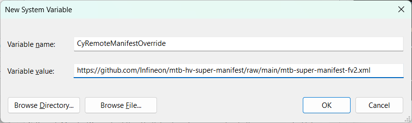
Note: By setting this environmental variable, you have overridden the standard manifest to which ModusToolbox™ points. By doing so, you will be able to access software assets for PSOC™ 4 HV devices. To revert to the default ModusToolbox™ installation, delete the CyRemoteManifestOverride environment variable.
If the
CY_TOOLS_PATHS
environment variable is already set, either delete it or edit it as follows:
Variable name:
CY_TOOLS_PATHS
Variable value:
<user-home>/ModusToolbox/tools_3.2
If it is not already set, do not create it. The latest installed version of the tool will be used automatically.
If there is a
manifest.loc
file in the
.modustoolbox
hidden directory, move the file out of the directory. The default location is
<user_home>/.modustoolbox/manifest.loc
Using these instructions
These instructions are grouped into several sections. Each section is devoted to a phase of the application development workflow. The major sections are:
- Part 1: Create a new application
- Part 2: View and modify the design
- Part 3: Write firmware
- Part 4: Build the application
- Part 5: Program the device
- Part 6: Test your design
This design is developed for the
PSOC™ 4 HV MS MCU Evaluation Kit
. You can use other supported kits to test this example by selecting the appropriate kit while creating the application.
About the design
This design uses the PSOC™ 4 HV MS MCU to execute two tasks: UART communication and LED control.
After device reset, this code example uses the UART to print a “Hello World” message to the serial port stream, and starts blinking the user LED on the kit. When you press the
Enter
key on the serial console, the blinking is paused or resumed.
Part 1: Create a new application
This section takes you on a step-by-step guided tour of the new application process. It uses the ‘
Empty App
’ starter application and guides you through the design development stages, and programming.
If you are familiar with developing projects with ModusToolbox™, you can use the ‘
Hello World
’ starter application directly. It is a complete design, with all the firmware written for the supported kits. You can walk through the instructions and observe how the steps are implemented in the code example.
If you start from scratch and follow all the instructions in this application note, you can use the code example as a reference while following the instructions.
Launch Eclipse IDE for ModusToolbox™ to get started. Note that Eclipse IDE for ModusToolbox™ software needs access to the internet to successfully clone the starter application onto your machine. The following shows the CYT4BF project as an example.
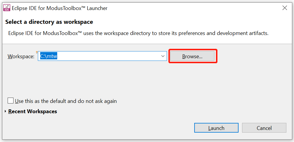
Select a new workspace
At launch, Eclipse IDE for ModusToolbox™ presents a dialog to choose a directory for use as the workspace directory. The workspace directory is used to store workspace preferences and development artifacts. You can choose an existing empty directory by clicking the
Browse
button, as
Figure 7
shows. Alternatively, you can type in a directory name to be used as the workspace directory along with the complete path, and the Eclipse IDE will create the directory for you
Figure 7. Select a directory as the workspace
Create a new ModusToolbox™ application
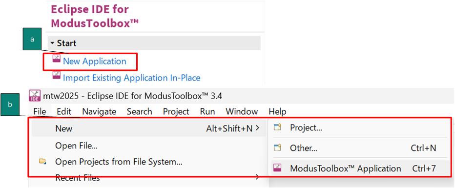
Click
New Application
in the Start group of the Quick Panel
Alternatively, you can choose
File > New > ModusToolbox™ Application
, as shown in
Figure 8
The Eclipse IDE for ModusToolbox™ Application window appears
Figure 8. Create a new ModusToolbox™ application
Select a target PSOC™ 4 HV MS MCU Evaluation Kit
ModusToolbox™ speeds up the development process by providing BSPs that set various workspace/project options for the specified development kit in the new application dialog.
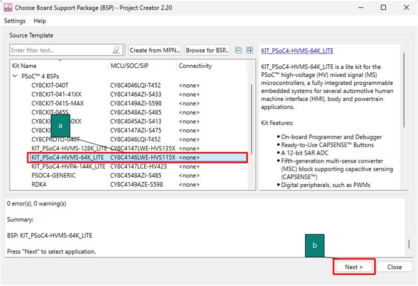
In the
Choose Board Support Package (BSP)
dialog, choose the
Kit Name
that you have. The steps that follow use
KIT_PSOC4-HVMS-64K_LITE
. See
Figure 9
for help with this step
Click
Next
Figure 9. Choose the target hardware
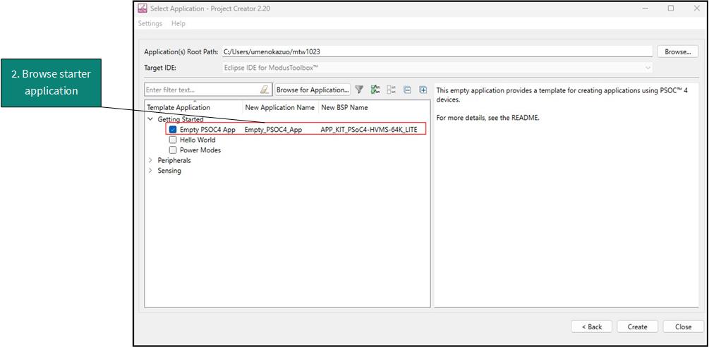
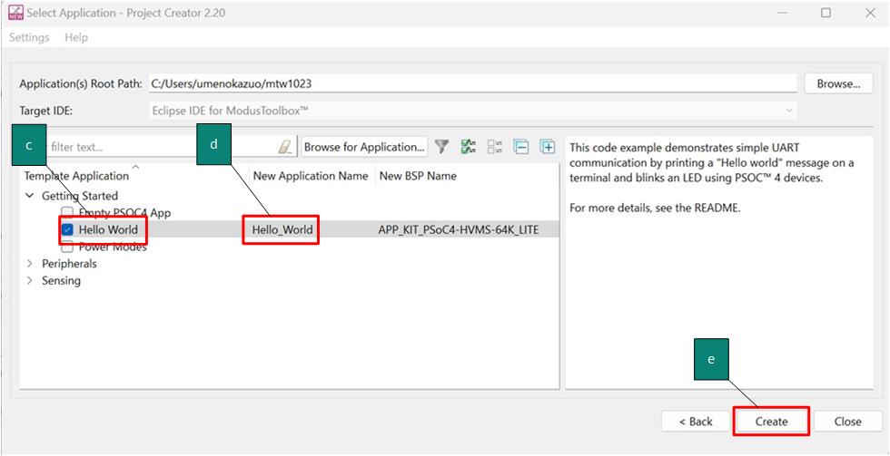
In the Starter Application dialog, select
, as
Figure 10
shows
In the
Name
field, type in a name for the application, such as
Hello_World
. You can choose to leave the default name if you prefer
Click
Create
to create the application, as shown in
Figure 10
. Wait for the Project Creator to automatically close once the project is successfully created
Figure 10. Choose the starter application
You have successfully created a new ModusToolbox™ application for a PSOC™ 4 HV MS MCU.
The BSP uses CY8C4146 as the default device that is mounted on the PSOC™ 4 HV MS MCU Evaluation Kit.
If you are using custom hardware based on a PSOC™ 4 HV MS MCU, or a different PSOC™ 4 HV MS MCU part number, see the “Creating your Own BSP” section in the
ModusToolbox™ user guide
. The guide is also available under the
ide_3.2>docs
folder of the ModusToolbox™ installation directory.
Part 2: View and modify the design
shows the ModusToolbox™ Project Explorer interface displaying the structure of the application project.
PSOC™ 4 HV MS MCU consist of one CM0+ core. This application note shows an example code for the firmware development using ModusToolbox™ software.
A project folder consists of various subfolders – each denoting a specific aspect of the project.
An application project contains a Makefile which is typically at the root folder. It has instructions on how to recreate the project. This file also contains the set of directives that the
make
tool uses to compile and link the application project. There can be more than one project in an application and each dependent project usually resides within its own folder within the application folder and contains its own
Makefile
The
bsps
folder contains all the configuration files that are generated by the device and peripheral configurators, and are included in the GeneratedSource folder of the BSP. These files are prefixed with
cycfg_
. These files contain the design configuration as defined by the BSP. You can view and modify the design configuration by clicking the
Device Configurator
link in the
Quick Panel
. However, note that if you upgrade the BSP library to a newer version, the manual edits done to the design.x files are lost. You can also create custom Device Configurator files for an application and override the ones provided by the BSP. See the “Modifying the BSP configuration for a single application” section in the
ModusToolbox™ user guide
for more details. The BSP folder also contains the linker scripts and the startup code for the PSOC™ 4 HV MS MCU device used on the board
The
build
folder contains all the artifacts resulting from the
make
build of the project. The output files are organized by target BSPs
Figure 11. Project explorer view
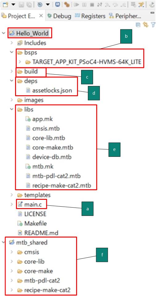
The
deps
folder contains
.mtb
files, which provide the location from which ModusToolbox™ software pulls the BSP/library that is directly referenced by the application. These files typically contain the GitHub location of the entire library. The
.mtb
files also contains a git commit hash or tag that tells which version of the library is to be fetched and a path as to where the library should be stored
The
latest-v1.X
tag in the link denotes the specific release of the BSP. The
$$ASSET_REPO$$
variable points to the root of the shared location. If the library has to be local to the application instead of shared, use
$$LOCAL$$
instead of
$$ASSET_REPO$$
The
libs
folder also contains
.mtb
files; these point to libraries that are included indirectly as a dependency of a BSP or another library. For each indirect dependency, the Library Manager places an
.mtb
file in this folder. These files have been populated based on the targets available in the
deps
folder
For example, using the BSP lib file,
TARGET_PSOC4-HVMS-64K_LITE.mtb
populates the
libs
folder with the following
.mtb
files:
cmsis.mtb
,
core- lib.mtb
,
core- make.mtb
,
device - db .mtb
,
mtb-pdl-cat 2 .mtb
,
recipe-make-cat 2 .mtb
The
libs
folder contains the
mtb.mk
file, which stores the relative paths of all the libraries required by the application. The build system uses this file to find all the libraries required by the application
By default, when creating a new application or adding a BSP/library to an existing application and specifying it as ‘shared’, all BSPs/libraries are placed in an
mtb_shared
directory adjacent to the application directories
The
mtb_shared
folder is shared between different applications that use the same versions of the BSP/library
Of interest are the configuration files that are in the
COMPONENT_BSP_x
folder. Click on the
Device Configurator
link in the
Quick Panel
.
Figure 12
shows the resulting window called the
Device Configurator
window. You can also double-click open the other
design.x
files to open them in their respective configurators or click the corresponding links in the
Quick Panel
.
Figure 12. Device Configurators overview
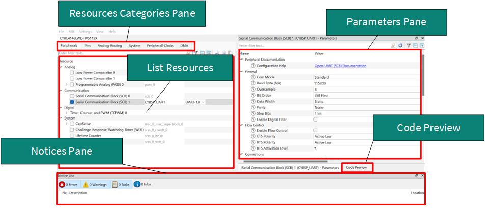
The
Device Configurator
window provides a
Resources Categories
pane. Here you can choose between different resources available in the device such as peripherals, pins, and clocks from the
List of Resources
.
You can choose how a resource behaves by choosing a
Personality
for the resource. For example, a
Serial Communication Block (SCB)
resource can have
EZI2C
,
I2C
,
SPI
, or
UART
personalities. The
Alias
is your name for the resource, which is used in firmware development. One or more aliases can be specified by using a comma to separate them (with no spaces).
The
Parameters
pane is where you enter the configuration parameters for each enabled resource and the selected personality. The
Code Preview
pane shows the configuration code generated per the configuration parameters selected. This code is populated in the
cycfg_
files in the
GeneratedSource
folder. Any errors, warnings, and information messages arising out of the configuration are displayed in the
Notices
pane.
The application project contains relevant files that help you create an application for the M0+ CPU (
main.c
).
Configuration of UART, timer peripherals, pins, and system clocks
The configuration of the debug UART peripheral, timer peripheral, pins, and system clocks can be done directly in the code using the function APIs provided by the BSP. See
Part 3: Write firmware
.
Part 3: Write firmware
At this point in the development process, in this part, you write the firmware that implements the design functionality.
If you are working from scratch using the empty PSOC™ 4 HV MS starter application, you can copy the respective source code to the
main.c
of the application project from the code snippet provided in this section. If you are using the Hello World code example, all the required files are already in the application.
Firmware flow
Now, examine the code in the
main.c
file of the application.
Figure 13
shows the firmware flowchart.
After reset, this code example initializes and configures the system clocks, pins, clock to peripheral connections, and other platform resources.
After reset, the clocks, system resources, the debug UART, and the user LED are initialized by the BSP initialization function. The debug UART prints a “Hello World!” message on the terminal emulator – the onboard KitProg3 acts the USB-to-UART bridge to create the virtual COM port, CPU toggles the LED state on the kit.
Figure 13. Firmware flowchart
This completes the summary of how the firmware works in the code example. See the source files for more information.
Function | Description |
|---|---|
cybsp_init() | This BSP function sets up the HAL hardware manager and initializes all the system resources of the device including but not limited to the system clocks and power regulators. |
Copy the following code snippet to the main.c of your application project.
Example code for the ‘Hello World’ application
#include "cy_pdl.h"
#include "cybsp.h"
/**************************************************************************
*****
* Macros
***************************************************************************
****/
#define LED_DELAY_MS (500u)
#define CY_ASSERT_FAILED (0u)
/**************************************************************************
*****
* Function Name: main
***************************************************************************
*****
* Summary:
* System entrance point. This function performs
* - initial setup of device
* - configure the SCB block as UART interface
* - prints out "Hello World" via UART interface
* - Blinks an LED under firmware control at 1 Hz
*
* Parameters:
* none
*
* Return:
* int
*
***************************************************************************
****/
int main(void)
{
cy_rslt_t result;
cy_stc_scb_uart_context_t CYBSP_UART_context;
/* Initialize the device and board peripherals */
result = cybsp_init();
/* Board init failed. Stop program execution */
if (result != CY_RSLT_SUCCESS)
{
CY_ASSERT(CY_ASSERT_FAILED);
}
/* Configure and enable the UART peripheral */
Cy_SCB_UART_Init(CYBSP_UART_HW, &CYBSP_UART_config,
&CYBSP_UART_context);
Cy_SCB_UART_Enable(CYBSP_UART_HW);
/* Enable global interrupts */
__enable_irq();
/* Send a string over serial terminal */
Cy_SCB_UART_PutString(CYBSP_UART_HW, "Hello world\r\n");
for(;;)
{
/* Toggle the user LED state */
Cy_GPIO_Inv(CYBSP_USER_LED1_PORT, CYBSP_USER_LED1_PIN);
/* Wait for 0.5 seconds */
Cy_SysLib_Delay(LED_DELAY_MS);
}
}
Part 4: Build the application
This section shows how to build the application.
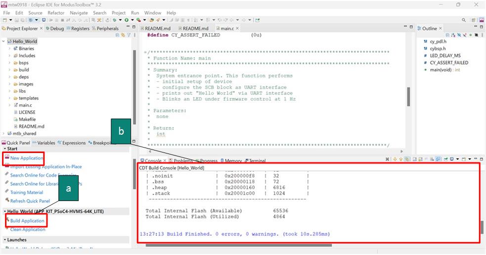
Build the application.
Select the application project in the Project Explorer window and click on the
Build <name> Application
shortcut under the
<name>
group in the Quick Panel. It selects the
Debug
build configuration and compiles/links all projects that constitute the application
The
Console
view lists the results of the build operation (see
Figure 14
)
Figure 14. Build the application
If you encounter errors, revisit before steps to ensure that you accomplished all the required tasks.
Note: You can also use the command-line interface (CLI) to build the application. See the “Using the command-line” section in the ModusToolbox™ user guide. This document is located in the/ide_<version>/docs/folder in the ModusToolbox™ installation.
Part 5: Program the device
This section shows how to program the PSOC™ 4 HV MS MCU device.
ModusToolbox™ software uses the OpenOCD protocol to program and debug applications on PSOC™ 4 HV MS MCU devices. For ModusToolbox™ software to identify the device on the kit, the kit must be running KitProg3. See
Programming/debugging
for details.
If you are using a development kit with a built-in programmer, connect the board to your computer using the USB cable.
If you are developing on your own hardware, you may need a hardware programmer/debugger; for example, a
CY8CKIT-005 MiniProg4
.
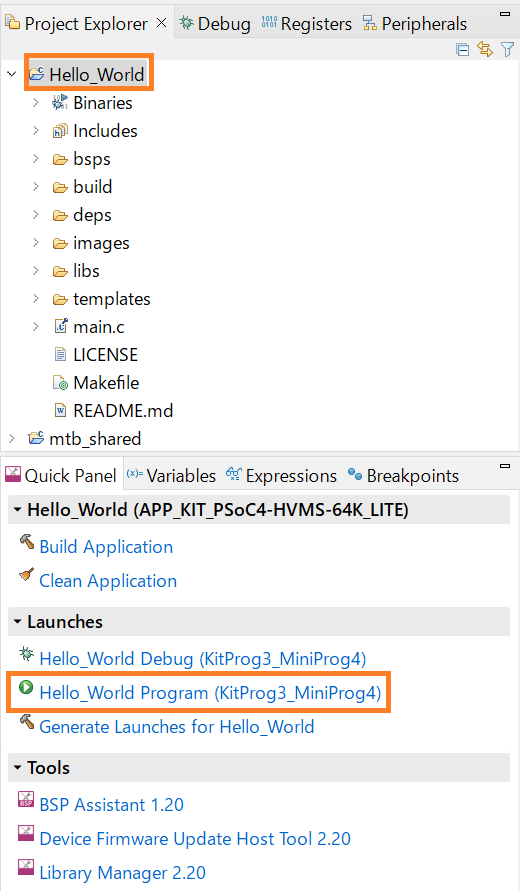
Program the application
Connect to the board and perform the following step
Select the application project and click on the
<application name> Program (KitProg3_MiniProg4)
shortcut under the
Launches
group in the
Quick Panel
, as
Figure 15
shows. The IDE will select and run the appropriate run configuration. Note that this step will also perform a build if any files have been modified since the last build
Figure 15. Programming an application to a device
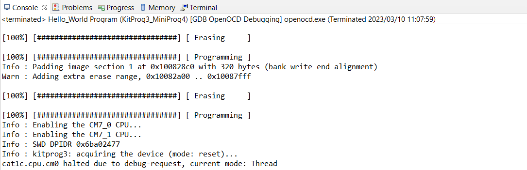
The
Console
view lists the results of the programming operation, as
Figure 16
shows.
Figure 16. Console – programming results
Part 6: Test your design
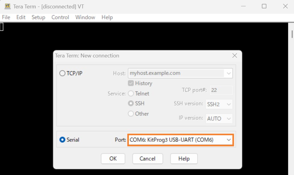
This application note uses Tera Term as the UART terminal emulator to view the results. You can use any terminal of your choice to view the output. Follow these steps to observe the output of your design:
Select the serial port
Launch Tera Term and select the USB-UART COM port as shown in
Figure 17
. Note that your COM port number may be different
Figure 17. Selecting the KitProg3 COM port in Tera Term
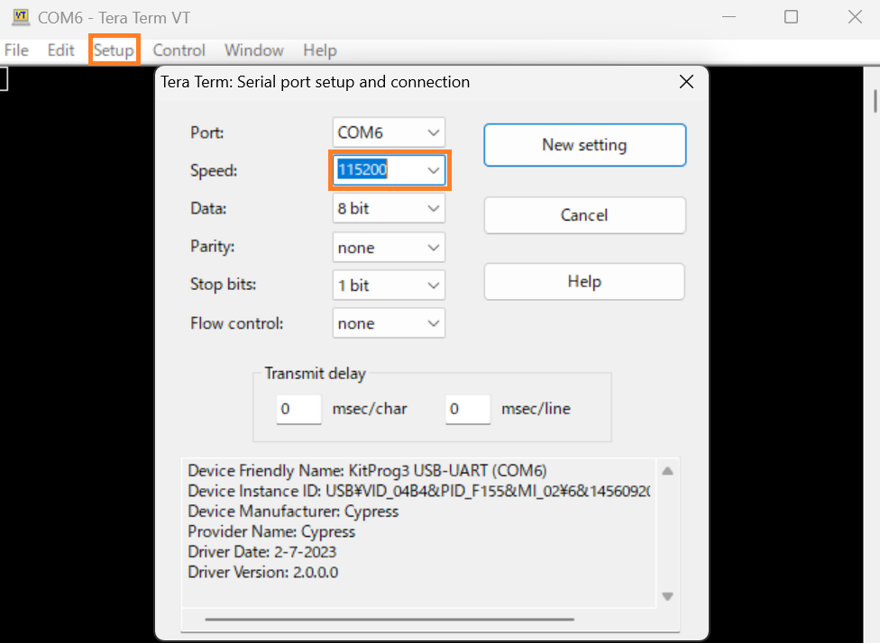
Set the baud rate
Set the baud rate to 115200 under
as shown in
Figure 18
Figure 18. Configuring the baud rate in Tera Term
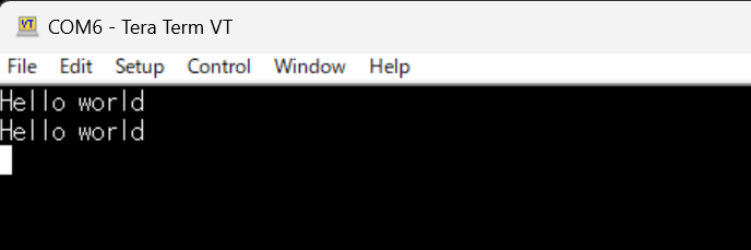
Reset the device
Press the reset switch (SW2) on the kit. A message appears on the terminal as shown in
Figure 19
. The user LED on the kit starts blinking
Figure 19. Printed UART message
Summary
This application note explores the PSOC™ 4 HV MS MCU device architecture and the associated development tools. The PSOC™ 4 HV MS MCU is a truly programmable embedded system-on-chip with configurable analog and digital peripheral functions, memory, and a triple-CPU system on a single chip. The integrated features and low-power modes make PSOC™ 4 HV MS MCU an ideal choice for BCM, gateway, and other automotive body control applications.
References
PSOC™ 4 HV webpage
Application notes
AN234115 - Getting started with PSOC™ HV MS family
AN234116 - Hardware design guide for PSOC™ HV MS family
Device datasheets
CY8C41x5/CY8C41x6, PSOC™ 4 High Voltage (HV) Mixed Signal (MS) Automotive MCU Based on 32-bit Arm® Cortex® -M0+ (Doc. No.: 002-33200)
PSOC™ 4 HV MS reference manuals
PSOC™ 4 HV MS MCU architecture reference manual (Doc. No.: 002-34138)
PSOC™ 4 HV MS MCU registers reference manual (Doc. No.: 002-34137)
For more PSOC™ 4 HV MS documents, contact
Technical Support
.
Glossary
This section lists the most commonly used terms that you might encounter while working with PSOC™ 4 HV MS family of devices.
Board support package (BSP) : A BSP is the layer of firmware containing board-specific drivers and other functions. The board support package is a set of libraries that provide firmware APIs to initialize the board and provide access to board level peripherals
Hardware Abstraction Layer (HAL) : The HAL wraps the lower-level drivers and provides a high-level interface to the MCU. The interface is abstracted to work on any MCU
KitProg: Onboard programmer/debugger with USB-I 2 C and USB-UART bridge functionality. KitProg is integrated onto most PSOC™ 4 HV MS development kits
MiniProg3 / MiniProg4 : Programming hardware for development that is used to program PSOC™ 4 HV MS devices on your custom board or PSOC™ 4 HV MS development kits that do not support a built-in programmer
Personality: Expresses the configurability of a resource for a functionality. For example, the SCB resource can be configured to be an UART, SPI, or I2C personalities
Middleware : Middleware is a set of firmware modules that provide specific capabilities to an application. Some middleware may provide network protocols (e.g., MQTT), and some may provide high-level software interfaces to device features (e.g., USB, audio)
Peripheral Driver Library (PDL): Simplifies software development for the PSOC™ 4 HV MS MCU architecture. The PDL reduces the need to understand register usage and bit structures, thus easing software development for the extensive set of peripherals available
Revision history
Document revision | Date | Description of changes |
|---|---|---|
1.0 | 2025-01-21 | Initial release |
1.1 | 2025-06-19 | Template update; no content update |
Trademarks
PSOC™, formerly known as PSoC™, is a trademark of Infineon Technologies. Any references to PSoC™ in this document or others shall be deemed to refer to PSOC™.