About this document
Scope and purpose
This document introduces you to the AIROC™ CYW20829, a high-performance, ultra-low-power, and “Secure” MCU + Bluetooth® LE platform, purpose-built for IoT applications. It combines a high-performance microcontroller with Bluetooth® LE (5.4) connectivity, high-performance analog-to-digital conversion audio input, I2S/PCM, CAN, and LIN for automotive use cases and other standard communication and timing peripherals. AIROC™ CYW20829 is the optimal solution for wireless input devices, remotes, keyboards, joysticks, Bluetooth® Mesh, automotive, asset tracking, and Bluetooth® LE IoT applications that need 10-dBm RF output power, such as lighting and home automation. This application note helps you get started with the AIROC™ CYW20829 MCU with Bluetooth® Low Energy. The overview of the device architecture, development kits, and software development tools shows how to create a simple Bluetooth® Low Energy application using Eclipse IDE for ModusToolbox™. It also guides you to more resources available online to accelerate your learning on AIROC™ CYW20829 MCU.
Intended audience
This document is intended for anyone who uses the AIROC™ CYW20829 MCU with Bluetooth® Low Energy connectivity.
Introduction
The Infineon AIROC™ CYW20829 MCU with Bluetooth® LE connectivity, hereafter called CYW20829 Bluetooth® LE, is a Bluetooth® 5.4 core spec-compliant device for Internet of Things (IoT), smart home, and industrial applications. It establishes the right combination of low-power and performance for today’s “always-on” applications. The AIROC™ CYW20829 Bluetooth® LE device is a programmable embedded system on chip that integrates the following on a single chip:
- Dual-CPU microcontroller: Two M33 cores
- Bluetooth® LE 5.4 subsystem
- Programmable analog and digital peripherals
- 256 KB of SRAM
CYW20829 Bluetooth® LE is suitable for a variety of power-sensitive connected applications such as:
- Smart watches and fitness trackers
- Smart home
- Lighting
- Remote controls
- Human Interface devices such as mouse, keyboard, VR, and gaming controllers
- Industrial automation
- Electronic shelf labeling
- Automotive
CYW20829 Bluetooth® LE provides a cost-effective and small-footprint alternative to the combination of an MCU and a Bluetooth® LE radio. The ModusToolbox™ software environment supports CYW20829 MCU application development with a set of tools for configuring the device, setting up peripherals, and complementing your projects with world-class middleware. To develop a Bluetooth® LE application, ModusToolbox™ provides a Bluetooth® configurator tool to easily set up Bluetooth® for your application, which uses the AIROC™ Bluetooth® stack.
Bluetooth® LE is an ultra-low-power wireless standard defined by the Bluetooth® Special Interest Group (SIG) for short-range communication. CYW20829 Bluetooth® LE integrates a Bluetooth® LE 5.4 radio and a royalty-free protocol stack with enhanced security, privacy, and throughput compliant with the Bluetooth® LE 5.4 specification.
CYW20829 Bluetooth® LE enables ultra-low-power connected applications with an integrated solution.
Figure 1 illustrates the keyboard application block diagram for a real-world use case using the CYW20829 SoC.
CYW20829 MCU is a highly capable and flexible solution. For example, the real-world use case in Figure 1 takes advantage of these features:
- A low-power Bluetooth® LE 5.4 system that can sustain up to three simultaneous connections
- A buck converter for ultra-low-power operation
- AIROC™ CYW20829’s low-power consumption, powered by 2 x AAA batteries, ensures a two-year battery life for the keyboard
- It features an ultra-low-power keyscan matrix of 8 rows and 18 columns that implements a 79-key layout out-of-the-box (OOB)
- The application allows easy configuration of reconnection advertisement time, pairing mode time, and disconnection time
This application note will help you get started with the CYW20829 MCU device and covers the following:
- Overview of the development ecosystem support for the CYW20829 MCU device, including software development platforms, hardware evaluation platforms, code examples, application notes, and other related technical documents
- Tutorial on how to develop applications using the CYW20829 EVK’s (CYW920829M2EVK-02 and CYW920829B0M2P4XXI100EVK) in Eclipse IDE for ModusToolbox™ by going through the step-by-step process of creating a simple Bluetooth® Low Energy-based application from scratch
This application note does not cover the Bluetooth® Low Energy or classic Bluetooth® protocol. It assumes that the reader is already familiar with the basics of these protocols.
Development ecosystem
AIROC™ CYW20829 resources
Infineon provides a wealth of product documentation at AIROC™ Bluetooth® LE & Bluetooth® to help you to select the right IoT device for your design. The following is an abbreviated list of resources for CYW20829 MCU:
- Datasheet describes and provides electrical specifications for the CYW20829 MCU
- Applications notes and Code examples cover a broad range of topics, from basic to advanced levels. You can browse the Infineon collection of code examples
Development tools
CYW920829M2EVK-02 and CYW920829B0M2P4XXI100EVK Bluetooth® LE SoC Evaluation Kit is a development kit that supports the CYW20829 series MCU that supports Bluetooth® LE connectivity.
Firmware/application development
For application development with the CYW20829 MCU, use the ModusToolbox™ development platform. The software includes configuration tools, low-level drivers, middleware libraries, and other packages that enable you to create MCU and wireless applications. All tools run on Windows, macOS, and Linux. ModusToolbox™ includes an Eclipse IDE, which provides an integrated flow with all the ModusToolbox™ tools. Other IDEs such as Visual Studio Code, IAR Embedded Workbench, and Arm® MDK (µVision) are also supported.
ModusToolbox™ software supports stand-alone devices and middleware configurators. Use the configurators to set the configuration of different blocks in the device and generate code that can be used in firmware development. The software supports all CYW20829 MCUs. It is recommended that you use ModusToolbox™ software for all application development for CYW20829 MCUs. See the ModusToolbox™ tools package user guide for more information.
For firmware development with CYW20829 Bluetooth® LE, you will be mainly using board support package (BSP), Hardware Abstraction Layer (HAL) for CYW20829 MCU features and AIROC™ BTSTACK library for the Bluetooth® feature.
Libraries and enablement software are available on the GitHub site.
ModusToolbox™ tools and resources can also be used on the command line. See the “ModusToolbox™ build system” section in the ModusToolbox™ tools package user guide for detailed documentation.
ModusToolbox™ software
ModusToolbox™ software provides support for many types of devices and environments. From a practical standpoint, ModusToolbox™ software delivers in various ways, such as installation resources, code examples, BSPs, and libraries; you only use the resources you need. When you create applications, you use these resources and interact with the hardware through the HAL and/or the Peripheral Driver Library (PDL).
Figure 2 shows the high-level view of the tools included in the ModusToolbox™ software.
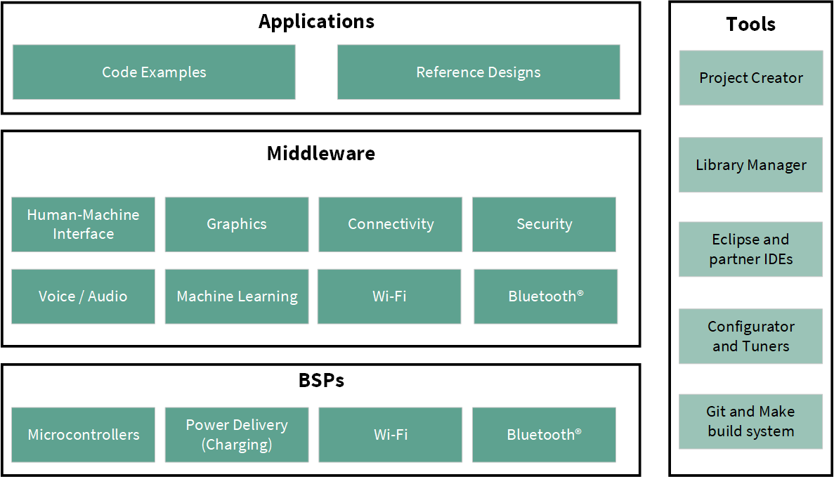
The ModusToolbox™ tools package installer includes the design configurators and tools, and the build system infrastructure.
The build system infrastructure includes the new project creation wizard that can be run independently of the Eclipse IDE, the make infrastructure, and other tools. This means you choose your compiler, IDE, RTOS, and ecosystem without compromising usability or access to our industry-leading CAPSENSE™ (Human-Machine Interface), AIROC™ Wi-Fi and Bluetooth®, security, and various other features.
Getting started with ModusToolbox™
Visit the ModusToolbox™ home page to download and install the latest version of the ModusToolbox™. See the ModusToolbox™ installation guide document in the Documentation tab of the ModusToolbox™ home page for information on installing the ModusToolbox™ software. After installing, launch ModusToolbox™ and navigate to the following items:
- User guide: The detailed user guide at
- These documents are also available in the Documentation tab of the ModusToolbox™ home page
Eclipse IDE for ModusToolbox™
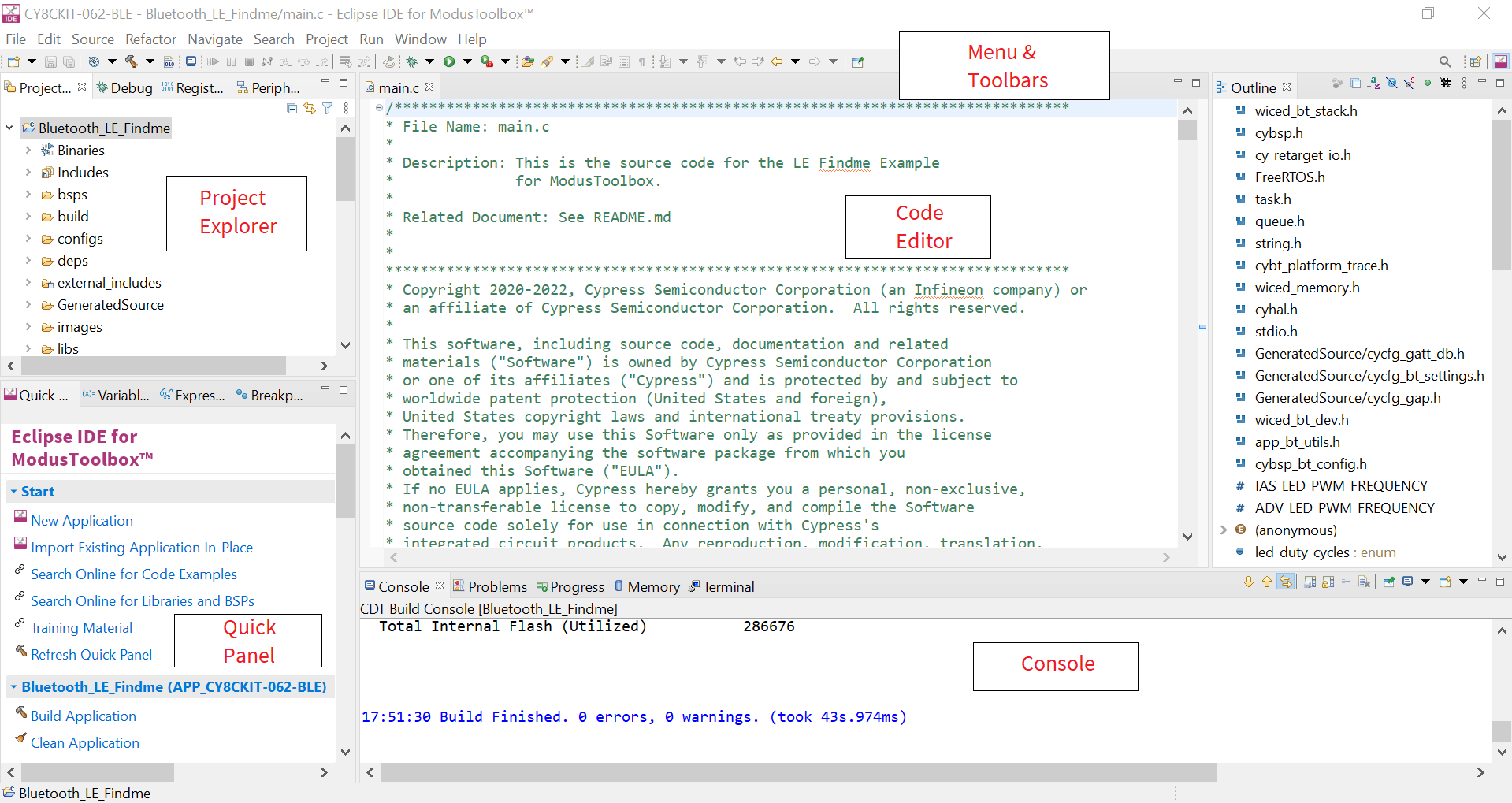
Eclipse IDE for ModusToolbox™ is based on the Eclipse IDE “Oxygen” version. It uses several plugins, including the Eclipse C/C++ Development Tools (CDT) plugin. The Eclipse Survival Guide provides tips and hints for using the Eclipse IDE for ModusToolbox™.
The IDE contains Eclipse-standard menus and toolbars, plus various panels such as the Project Explorer, Code Editor, and Console, as shown in Figure 3. One difference from the standard Eclipse IDE is the “ModusToolbox™ Perspective.” This perspective provides the “Quick Panel,” a “New View,” and adds tabs to the Project Explorer.
The top-level entity that you ultimately program to a device is called an application in the IDE. The application consists of one or more Eclipse projects. The IDE handles all dependencies between projects automatically. It also provides hooks for launching various tools provided by the software development kits (SDKs).
With Eclipse IDE for ModusToolbox™, you can:
- Create a new application based on a list of starter applications filtered by kit or device or browse the collection of code examples online.
- Configure device resources to build your hardware system design in the workspace.
- Add software components or middleware.
- Develop your application firmware.
CYW20829 Bluetooth® LE software resources
This section details the additional software resources required to start with firmware development for CYW20829 Bluetooth® LE. See the Configurators section for more details.
AIROC™ BTSTACK
Infineon’s AIROC™ BTSTACK is a software implementation of the Bluetooth® core 5.4 host protocol stack. The stack is hosted as a library on Infineon’s GitHub. The stack library includes both Bluetooth® BR/EDR and Bluetooth® LE host and provides API for it. The application can choose to use Bluetooth® LE. The stack is available for different Arm® cores such as CM4 and CM33, and can be used with three toolchains Arm®, GCC, and IAR. For CYW20829 Bluetooth® LE will be using only the Bluetooth® LE build of the stack and the corresponding LE API.
The AIROC™ BTSTACK provides API for Bluetooth® LE host layers:
- L2CAP
- GATT
- GAP
- SMP
In addition to API related to Bluetooth® LE host stack layers, the AIROC™ BTSTACK also provides functions to configure Bluetooth® LE parameters such as PHY, device address, and so on. It has utility functions for memory management.
The application uses the AIROC™ BTSTACK API extensively to implement the Bluetooth® functionality required.
Bluetooth® porting layer
AIROC™ BTSTACK requires a porting layer specific to the device that it is running on. The porting layer sets up the physical transport required for HCI traffic, memory, threads, and other OS constructs required by the stack library.
The porting layer for Infineon Bluetooth® devices is hosted on GitHub as a library called btstack-integration with source. btstack-integration caters to various Bluetooth® devices with different hardware platforms such as CYW20829 Bluetooth® LE, CYW20829, and PSoC™ 6 + CYW43xxx. It provides a component for each platform and the application can include the respective component to get the functionality.
In CYW20829 Bluetooth® LE, the application runs on the one CM33 core of CYW20829, and the Bluetooth® LE subsystem runs on another CM33 core of CYW20829. A hardware block called inter-processor communication (IPC) is used as HCI. Therefore, the application uses the component called BTSS-IPC in btstack-integration.
FreeRTOS support with ModusToolbox™
Adding native FreeRTOS support to a ModusToolbox™ application project is like adding any middleware library. You can include the FreeRTOS middleware in your application by using the Library Manager. If using the Eclipse IDE, select the application project and click the Library Manager link in the Quick Panel. Click Add Library and select freertos from the Core dialog.
The .mtb file pointing to the FreeRTOS middleware is added to the application project’s deps directory. The middleware content is also downloaded and placed inside the corresponding folder called freertos. The default location is in the shared asset repo named mtb_shared. To continue working with FreeRTOS, follow the steps in the Quick Start section of FreeRTOS documentation.
Configurators
ModusToolbox™ software provides graphical applications called configurators that make it easier to configure a hardware block. For example, instead of having to search through all the documentation to configure a Serial Communication Block (SCB) as a UART with a desired configuration, open the appropriate configurator and set the baud rate, parity, and stop bits. After saving the hardware configuration, the tool generates the "C" code to initialize the hardware with the desired configuration.
There are two types of configurators: BSP configurators (Device configurator, QSPI configurator, and Smart I/O configurator) that configure items that are specific to the MCU hardware and library configurators (Bluetooth® configurator) that configure options for middleware libraries.
Configurators are independent of each other, but they can be used together to provide flexible configuration options. They can be used stand-alone, with other tools, or within a complete IDE. Configurators are used for:
- Setting options and generating code to configure drivers
- Setting up connections such as pins and clocks for a peripheral
- Setting options and generating code to configure middleware
For CYW20829 MCU applications, the available configurators include:
- Device Configurator: Set up the system (platform) functions, pins, and basic peripherals (for example, UART, timer, and PWM)
- QSPI configurator: Configure external memory and generate the required code
- Smart I/O configurator: Configure Smart I/O pins
- Bluetooth® configurator: Configure the Bluetooth® settings
Each of the above configurators creates its files (for example, design.cyqspi for QSPI). BSP configurator files (for example, design.modus) are provided as part of the BSP with default configurations while library configurators (for example, design.cybt) are provided by the application. When an application is created based on Infineon BSP, the application makes use of BSP configurator files from the Infineon BSP repo. You can customize/create all the configurator files based on your application requirement using ModusToolbox™ software. See BSP Assistant to create your custom BSP. See ModusToolbox™ help for more details.
In the next section, see a detailed look at using the configurators as part of a Bluetooth® Low Energy application creation exercise.
CYW20829 MCU development kits
| Product line | Development kits |
|---|---|
|
Connectivity |
AIROC™ CYW20829 Bluetooth® LE SoC Evaluation Kit (CYW920829M2EVK-02) |
|
AIROC™ CYW20829 Bluetooth® LE Trace Antenna Module Evaluation Kit (CYW920829B0M2P4TAI100EVK) |
|
|
AIROC™ CYW20829 Bluetooth® LE External Pad Module Evaluation Kit (CYW920829B0M2P4EPI100EVK) |
Device features
CYW20829 MCUs have extensive features as shown in Figure 6. The following is a list of major features. For more information, see the AIROC™ CYW20829 Bluetooth® LE SoC page.
- 32-bit application subsystem
- 96-MHz Arm® Cortex®-M33 CPU with single-cycle multiply, and memory protection unit (MPU)
- Arm® v8-M architecture
- CMOS 40-nm process
- User-selectable core logic operation at either 1.1 V or 1.0 V
- Active CPU current slope with the 1.1-V core operation
- Cortex®-M33: 40 µA/MHz
- Active CPU current slope with the 1.0-V core operation
- Cortex®-M33: 22 µA/MHz
- Datawire (DMA) controllers with 16 channels
- 32-KB cache for greater Execute in Place (XIP) performance with lower power
- Memory subsystem
- 256-KB SRAM with power and data retention control
- OTP eFuse array for security provisioning
- Bluetooth® Low Energy
subsystem
- 2.4 GHz RF transceiver with 50-Ω antenna drive
- Digital PHY
- Link layer engine supporting master and slave modes
- Programmable TX power: up to 10 dBm
- Excellent receiver sensitivity :
- LE-1 Mbps: -98 dBm
- LE-2 Mbps:-95 dBm
- Coded PHY 500 kbps (LE-LR): -101 dBm
- Coded PHY 125 kbps (LE-LR): -106 dBm
- Received signal strength indication (RSSI) with 1-dB resolution
- 5.2-mA Tx (0 dBm) and 5.6 mA RX (LE 1 Mbps) current with 3.0 V supply and using an internal buck converter
- The link layer engine supports up to 16 connections simultaneously, four are peripheral
-
Low-power 1.7 V to 3.6 V operation
- Six power modes for fine-grained power management
- Deep Sleep mode current of ~4.5 µA with 64-KB SRAM retention
- On-chip DC-DC buck converter
- Flexible clocking options
- 8-MHz internal main oscillator (IMO) with ±2% accuracy
- Ultra-low-power 32-kHz internal low-speed oscillator (ILO)
- Two oscillators: High-frequency (24 MHz) for radio PLL and low-frequency (32 kHz watch crystal) for LPO
- 48 MHz low-power internal high-speed oscillator (IHO)
- Frequency-locked loop (FLL) for multiplying IMO frequency
- Integer and fractional peripheral clock dividers
- Quad SPI (QSPI)/serial memory interface (SMIF)
- XIP from external quad SPI flash
- On-the-fly encryption and decryption
- Support for DDR
- Supports single, dual, and quad interfaces with a throughput of up to 384 Mbps
- Serial communication
- Their run-time configurable Serial Communication Blocks (SCBs)
- First SCB: Configurable as SPI or I2C
- Second SCB: Configurable as SPI or UART
- Third SCB: Configurable as I2C or UART
- SCB #0 can operate in system Deep Sleep mode with an external clock; this SCB can be either SPI slave or I2C Slave
- Their run-time configurable Serial Communication Blocks (SCBs)
- Audio subsystem
- Two pulse density modulation (PDM) channels and one I2S channel with time division multiplexed (TDM) mode
- Timing and pulse-width modulation
- Seven 16-bit and two 32-bit Timer/Counter Pulse-Width modulator (TCPWM) blocks for MCU. Need multiple PWMs for color LEDs
- PWM supports center-aligned, edge, and pseudo-random-modes
- ADC and MIC
- Sigma-delta switched cap ADC for audio and DC measurements
- Up to 32 programmable GPIOs
- One I/O port (8 I/Os) enables Boolean operations on GPIO pins; available during system Deep Sleep
- Programmable drive modes, strengths, and slew rates
- Two overvoltage-tolerant (OVT) pins
- Up to 6 may be used for SMIF
- Security built into platform architecture
- ROM-based root of trust via uninterruptible “Secure Boot”
- Step-wise authentication of execution images
- Secure execution of code in an execute-only mode for protected routines
- All debug and test ingress paths can be disabled
- Up to four protection contexts (one available for customer code)
- Secure debug support via an authenticated debug token
- Encrypted image support for external SMIF memory
- Cryptography hardware
- Hardware acceleration for symmetric cryptographic methods and hash functions
- True random number generation (TRNG) function
My first CYW20829 Bluetooth® Low Energy application
This section provides step-by-step instructions to build a simple Bluetooth® Low Energy-based application for the CYW20829 Bluetooth® LE device using the Eclipse IDE for ModusToolbox™. A Bluetooth® SIG-defined standard profile called Find Me Profile (FMP) is implemented in the design. The steps covered in this section are:
- Part 1: Create a new application
- Part 2: Configure design resources
- Part 3: Write the application code
- Part 4: Build, program, and test your design
These instructions require that you use a Bluetooth® LE Find Me Profile code example. However, the extent to which you use the code example (CE) depends on the path you follow through these instructions. Note that the terms Code Example (CE) and application mean the same thing in the context of this document. A Code Example (CE) is simply an existing ModusToolbox™ application that serves a specific purpose or functionality.
Defined two paths through these instructions depending on what you need to learn:
| Path | “Using CE directly” path(Evaluate existing code example (CE) directly) | “Working from scratch” path(Use existing code example (CE) as a reference only) |
|---|---|---|
|
Best for |
A few are new to the tool or device and want to see how it all works quickly. |
A few who want the hands-on experience to learn to develop CYW20829 based Bluetooth® LE applications in ModusToolbox™. |
What you need to do for each path is clearly defined at the start of each part of the instructions.
If you start from scratch and follow all instructions in this application note, you can use the code example as a reference while following the instructions. Working from scratch helps you learn the design process and takes more time. Alternatively, you can evaluate the existing code example directly to get acquainted with the CYW20829 Bluetooth® LE application development flow in a short time.
It would help if you start reading Prerequisites and About the design in both cases.
Prerequisites
Ensure that you have the following items for this exercise.
- ModusToolbox™ 3.0 or later version is installed on your PC.
- CYW20829 EVK's with Kitprog3. See the KitProg3 user guide on how to update the KitProg firmware.
- This design is developed for the CYW920829M2EVK-02. If you wish to use other hardware, you must adapt the instructions to your needs.
- AIROC™ Bluetooth® Connect iOS/Android app or any Android or iOS app that supports the Immediate Alert Service (IAS).
-
Internet access to the GitHub repositories during project creation.
Scan the following QR codes from your mobile phone to download the AIROC™ Bluetooth® Connect app.

About the design
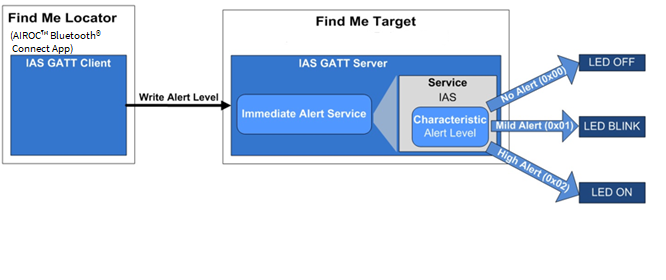
This design implements a Bluetooth® Low Energy Find Me Profile (FMP) that consists of an Immediate Alert Service (IAS). FMP and IAS are Bluetooth® Low Energy standard Profile and Service respectively, as defined by the Bluetooth® SIG.
The design uses the two LEDs (red LED and orange LED) on the CYW20829 EVK's. The orange LED (USER LED2) displays the IAS alert level – no alert (LED OFF), mild alert (LED blinking), or high alert (LED ON). The red LED (USER LED1) indicates whether the Peripheral device (CYW20829 MCU) is advertising (LED blinking), connected (LED ON), or disconnected (LED OFF). In addition, a debug UART interface uses sending the Bluetooth® stack and application trace messages.
An iOS/Android mobile device or a PC can act as the Bluetooth® Low Energy Central device, connecting to the Peripheral device.
Part 1: Create a new application
This part takes you step-by-step through creating a new ModusToolbox™ application. Before performing the steps in this section, decide whether you want to create and run the code example as-is or you would instead learn how to create an application from scratch. Depending on your choice, follow these steps:
| Path | “Using CE directly” path(Evaluate existing code example (CE) directly) | “Working from scratch” path(Use existing code example (CE) as reference only) |
|---|---|---|
|
Actions |
Follow the Select a new workspace, Create a new ModusToolbox™ application, Select CYW20829 MCU-based target hardware, and
Create the Bluetooth® LE Find Me code example (applicable only for the “Using CE directly” flow). Ignore section Select a starter application and create the application (applicable only for “Working from scratch” flow).
|
Follow the Select a new workspace, Create a new ModusToolbox™ application, Select CYW20829 MCU-based target hardware, and
Select a starter application and create the application (applicable only for “Working from scratch” flow). Ignore section Create the Bluetooth® LE Find Me code example (applicable only for the “Using CE directly” flow).
|
Launch ModusToolbox™ and get started.
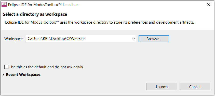
Select a new workspace
At launch, ModusToolbox™ presents a dialog to choose a directory for use as the workspace directory. The workspace directory stores the workspace preferences and development artifacts, such as device configuration and application source code.
You can choose an existing empty directory by clicking the Browse button, as Figure 7 shows. Alternatively, you can type in a directory name to be used as the workspace directory along with the complete path, and ModusToolbox™ will create the directory for you.
Create a new ModusToolbox™ application
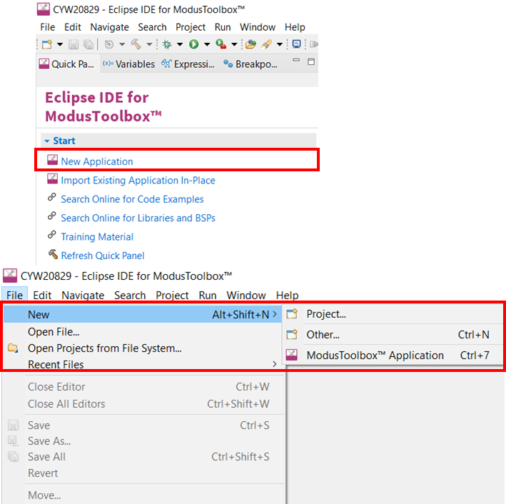
Click New Application in the Start group of the Quick Panel. Alternatively, you can choose (Figure 8).
The Eclipse IDE for ModusToolbox™ Application window appears.
Select CYW20829 MCU-based target hardware
ModusToolbox™ presents the list of Infineon kits to start your application development. In this case, developing an application on the CYW920829M2EVK-02 and CYW920829B0M2P4XXI100EVK that uses the CYW20829 device. Select CYW920829M2EVK-02 BSP and click Next (Figure 9).

Create the Bluetooth® LE Find Me code example (applicable only for the “Using CE directly” flow)
Here, you Create an existing code example into the Eclipse IDE for ModusToolbox™. Use this feature to create the Bluetooth® LE Find Me code example for the Using CE directly flow. Figure 10 shows the Select Application dialog of the project creator tool. Select the Bluetooth® LE Find Me application, and optionally, in the ‘New application Name’ field, change the name of the application. Click Create and wait for the application to get downloaded and created in the workspace.
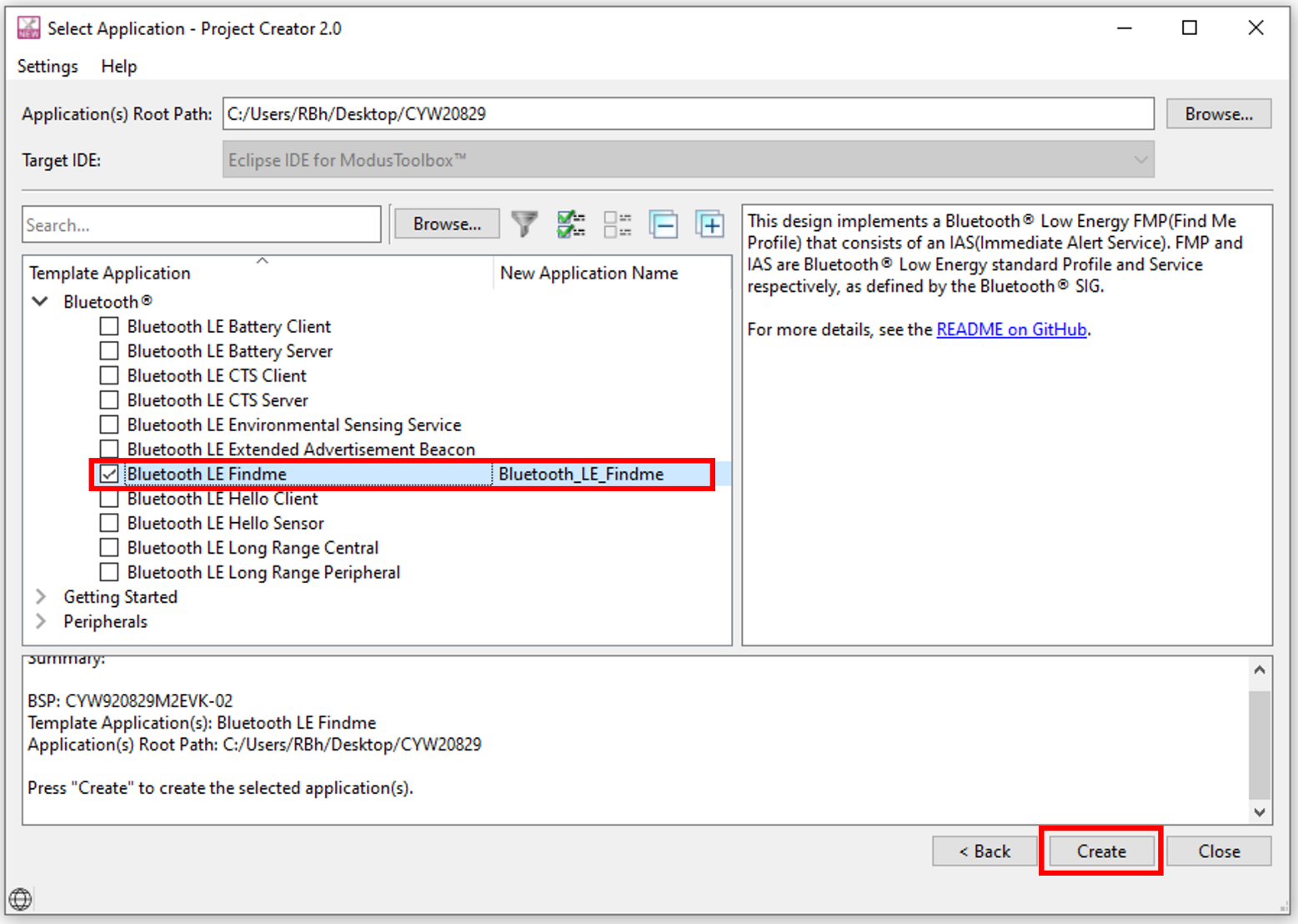
You have successfully imported a new ModusToolbox™ application for CYW920829M2EVK-02 BSP.
Select a starter application and create the application (applicable only for “Working from scratch” flow)
Here, you use an existing template application as the starting point for the Working from scratch development flow. In the Select Application dialog shown in Figure 11, select Empty_ App. In the Name field, type in a name for the application and click Next; the application summary dialog appears. Click Create and wait for the application to get downloaded and created in the workspace. Click Close to complete the application creation process.
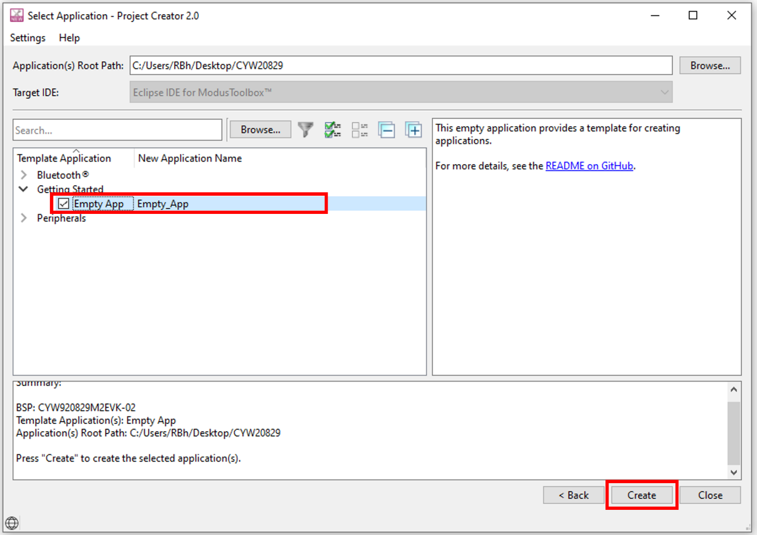
You have successfully created a new ModusToolbox™ application for CYW920829M2EVK-02 BSP.
Part 2: Configure design resources
In this step, you will configure the design resources for your application and generate the configuration code.
| Path | “Using CE directly” path(Evaluate existing Code Example (CE) directly) | “Working from scratch” path(Use existing Code Example (CE) as reference only) |
|---|---|---|
|
Actions |
Read and understand all steps. The CE has the resource configurations done. Therefore, you need not perform any of the steps in this section. |
Perform all steps |
The Empty_App application template has all the resources available on the CYW20829 EVK's pre-configured and ready for use. These resources include user LEDs, push buttons, and communication peripherals (such as Bluetooth®, UART, I2C, and SPI). The template application also contains a default application code snippet that initializes the device and the Bluetooth® stack and prints a status message on the UART interface.
Before proceeding further, a quick tour of the ModusToolbox™ Project Explorer is in order. Figure 12 shows that the ModusToolbox™ Project Explorer view after the template application is created.
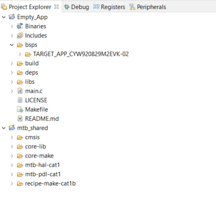
- The files provided by the BSP are in the bsps folder and are listed under TARGET_<bsp_name> subfolders. All the input files for the device and peripheral configurators are in the config folder inside the BSP
- The GeneratedSource folder in the BSP contains the files that are generated by the configurators and are prefixed with cycfg_. These files contain the design configuration as defined by the BSP. From ModusToolbox™ 3.x or later, you can directly customize the configurator files of BSP for your application rather than overriding the default design configurator files with custom design configurator files because BSPs are completely owned by the application
- The BSP folder also contains the linker scripts and the start-up code for the CYW20829 MCU used on the board
- The build folder contains all the artifacts resulting from a build of the project. The output files are organized by target BSPs
- The deps folder contains .mtb files, which provide the locations from
which ModusToolbox™ pulls the libraries that are
directly referenced by the application. These files typically each contains the GitHub
location of a library. The .mtb files also contain a git Commit Hash or Tag that
provides which version of the library is to be fetched and a path as to where the
library should be stored locally
For example, here, retarget-io.mtb points to
mtb://retarget-io#latest-v1.X#$$ASSET_REPO$$/retarget-io/latest-v1.X. The variable$$ASSET REPO$$points to the root of the shared location which defaults to mtb_shared. If the library must be local to the application instead of shared, use$$LOCAL$$instead of$$ASSET REPO$$ - The libs folder also contains .mtb files. In this case, they point
to libraries that are included indirectly as a dependency of a BSP or another library.
For each indirect dependency, the Library Manager places an .mtb file in this folder.
These files have been populated based on the targets available in the deps folder
For example, the BSP CYW920829M2EVK-02 populates the libs folder with the following .mtb files:cmsis.mtb, core-lib.mtb, core-make.mtb, mtb-hal-cat1.mtb, mtb-pdl-cat1.mtb, cat1cm0p.mtb, reciepe-make-cat1a.mtb
The libs folder contains the file mtb.mk, which stores the relative paths of all the libraries required by the application. The build system uses this file to find all the libraries required by the application. Everything in the libs folder is generated by the Library Manager, therefore, you should not manually edit anything in that folder.
- An application contains a Makefile which is in the application’s root folder. This file contains the set of directives that the make tool uses to compile and link the application project. There can be more than one project in an application. In that case, there is a Makefile at the application level and one inside each project
- By default, when creating a new application or adding a library to an existing application and specifying it as shared, all libraries are placed in an mtb_shared directory adjacent to the application directories
The mtb_shared folder is shared between different applications within a workspace. Different applications may use different versions of shared libraries if necessary.
Now, let us get into how to configure the design resources in the template application.
Configure hardware resources
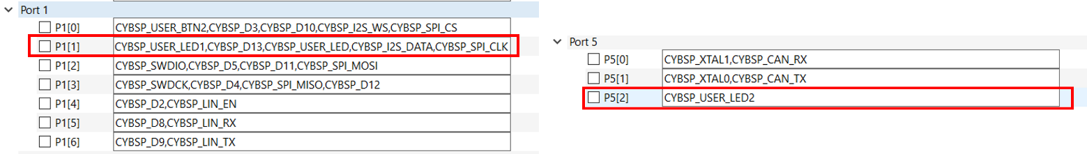
Bluetooth® LE Find Me code example uses two LEDs. Currently, using HAL functions to configure and initialize the GPIOs routed to the LEDs on the board. The BSP provides aliases for GPIO pins routed to different components on the board. See these aliases in the file . For the two LEDs, Table 5 shows the aliases, which are provided in the BSP:
| Pin | Alias | Purpose |
|---|---|---|
|
P1.1 |
CYBSP_USER_LED |
Mapped to the Orange LED (LED4) on the kit. Indicates IAS Alert Level. |
|
P5.2 |
CYBSP_USER_LED2 |
Mapped to the Red LED (LED3) on the kit. Indicates the Advertising/Connected state of the Bluetooth® Low Energy peripheral device. |
The mentioned aliases are generated through the
design.modus file, which is in the
bsps/TARGET_<BSP-name>/config. You can view the
alias setting in the Device Configurator tool. The Device Configurator is used to
enable/configure the peripherals and the pins used in the application. To launch the Device
Configurator, double-click the design.modus file or click on Device Configurator in the Quick Panel, as shown in Figure 13. This file
is used by the graphical configurators, which generate the configuration firmware. This
firmware is stored in the application’s GeneratedSource folder. Anytime you change the
Device Configurator, click to save the updated configuration.
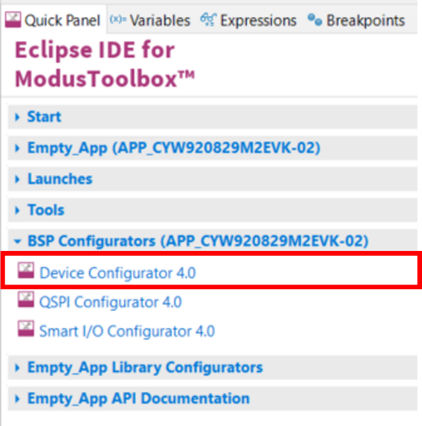
Figure 14 shows the Device Configurator showing the Peripherals for this application.
The Device Configurator provides a set of Resources Categories tabs. Here, you can choose between different resources available in the device such as peripherals, pins, and clocks from the List of Resources.
You can choose how a resource behaves by choosing a Personality for the resource. For example, a Serial Communication Block (SCB) resource can have EZI2C, I2C, SPI, or UART personalities. The Alias can be a user-specified resource name used in firmware development. Specify one or more aliases by using a comma to separate them (with no spaces).
The Parameters panel is where you enter the configuration parameters for each enabled resource and the selected personality. The Code Preview panel shows the code generated according to the configuration parameters selected. This code is populated in the cycfg_ files in the GeneratedSource folder. The Parameters panel and Code Preview panel may be displayed as tabs instead of separate windows, but the contents will be the same.
Any errors, warnings, and information messages arising out of the configuration are displayed in the Notices panel.
Currently, the device configurator supports configurations using a PDL source. If you choose to use HAL libraries in your application, then you do not need to do any device configuration changes here.
Click on Pins and expand the sections: Port 1 and Port 5. Under Port 1, you can see the alias CYBSP_USER_LED against Pin 1.1 and under Port 5, you can see the alias CYBSP_USER_LED2 against Pin 5.2 as shown in Figure 15.
Add libraries and middleware
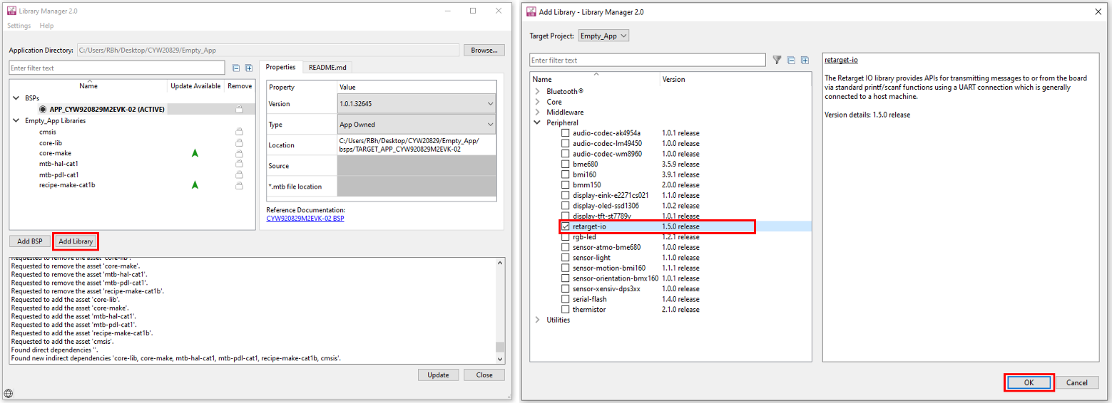
ModusToolbox™ provides a ‘Library Manager’ dialog to select various middleware components for developing Bluetooth® applications. To launch the Library Manager dialog, in the Quick Panel, click the Library Manager. Left-click on Add Library to add the required libraries and middleware for your application. For Bluetooth® LE Find Me, follow these steps to add the required libraries.
- In this step, you will add the retarget-io middleware to redirect standard input and output streams to the UART configured by the BSP. The initialization of the middleware will be done in main.c. After clicking on Add Library, select (see Figure 16 for this option)
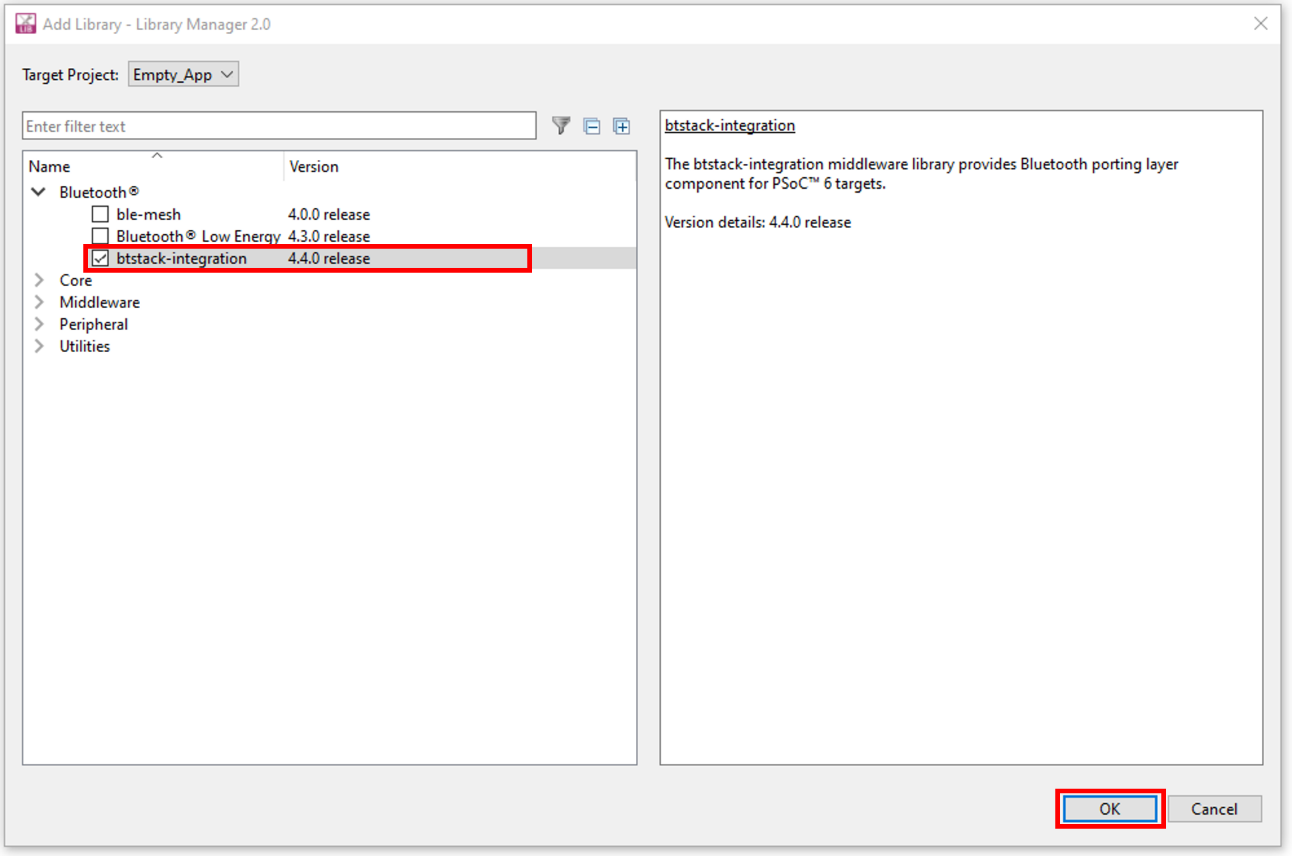
- Next, you add the AIROC™ BTSTACK, which is a software implementation of the Bluetooth® core 5.4 Host protocol stack. AIROC™ BTSTACK requires a porting layer specific to the device that it is running on. Therefore, you will add the btstack integration porting layer, which sets up the physical transport required for HCI traffic, memory, threads, and other OS constructs required by the stack library. Click on Add Library and select (see Figure 17 for this option). Note that selecting btstack-integration selects the required version of btstack. Do not have to explicitly select btstack unless a specific version is required. Along with btstack, btstack-integration also adds dependency libraries abstraction-rtos and freertos. The files necessary to use the btstack integration middleware are added in the mtb_shared > btstack-integration folder and the .mtb file is added to the deps folder
- You have selected all the required libraries. To add them to the project, click OK and then Update. Figure 18 shows all the libraries selected and their dependency libraries. The files necessary to use the retarget-io middleware are added in the mtb_shared > retarget_io folder, and the .mtb file is added to the deps folder. Similarly, you can find other libraries under the respective folders in the mtb_shared folder

Bluetooth® Configurator
The Bluetooth® peripheral has an additional configurator called the Bluetooth® Configurator that is used to create the Bluetooth® Low Energy configuration structure and GATT database for the application. The Bluetooth® LE configuration structure generated will be used by the application during stack initialization.
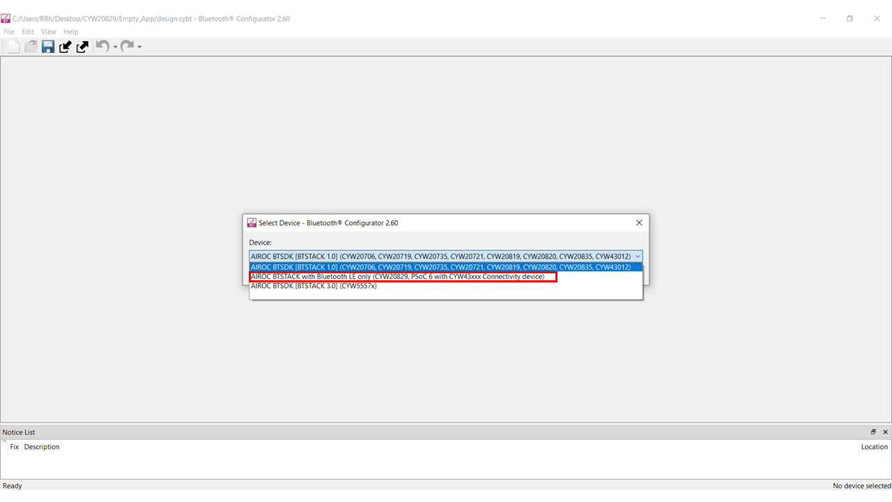
For the Find Me Profile application, you need to generate a GATT database and Bluetooth® settings to initialize the host BTSTACK corresponding to the Find Me Target role of the CYW20829 EVK's. To launch the Bluetooth® Configurator, In Quick Panel click on the Bluetooth Configurator under the Library Configurator section.
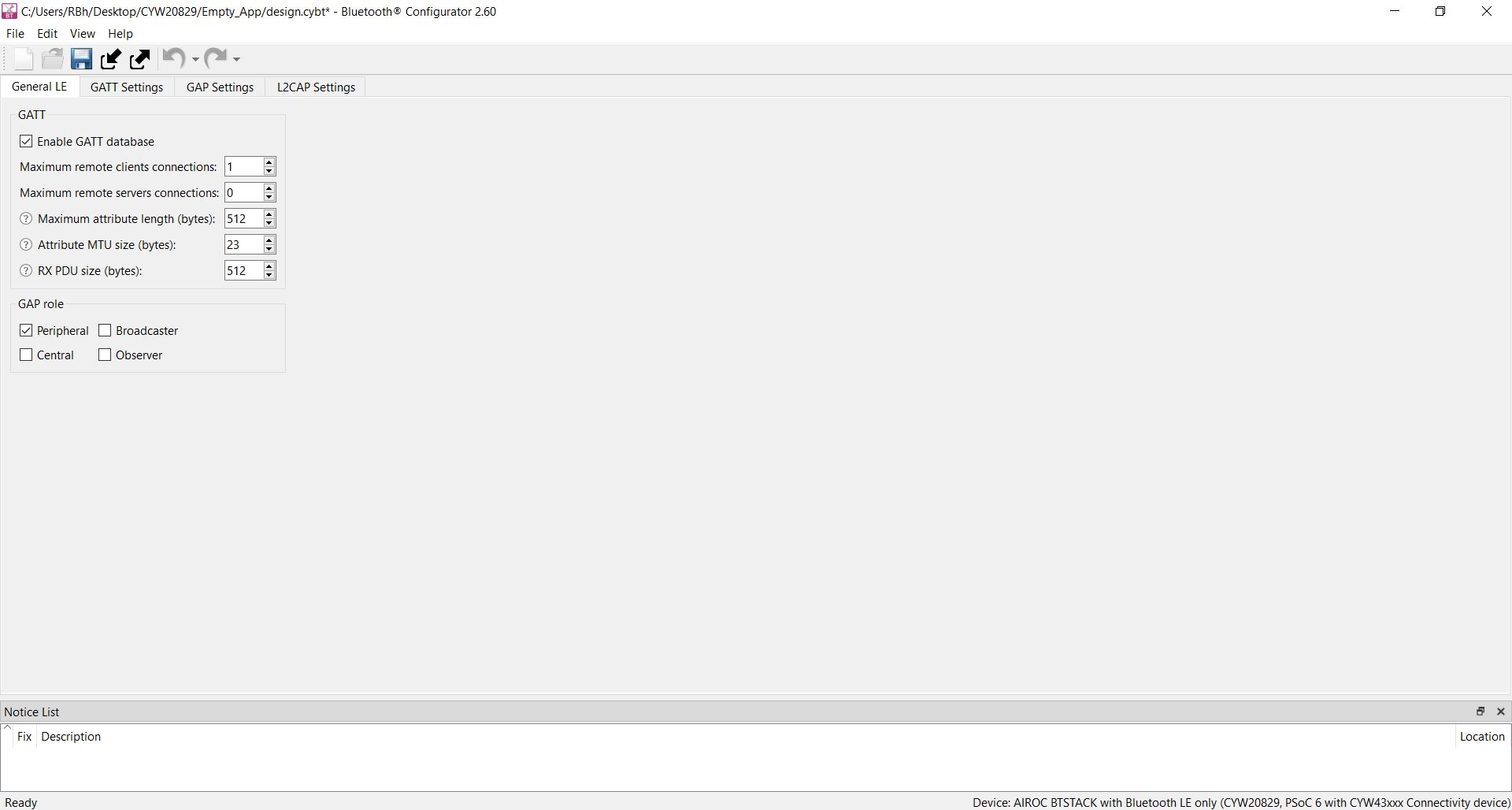
Set the General LE properties as shown in Figure 20.
- Enable the GATT database
- Maximum remote client connections set to ‘1’. This will configure the Bluetooth® LE Stack appropriately
- Confirm that Peripheral is selected as the GAP role. This sets the device to act as a Bluetooth® LE Peripheral device and respond to central device requests
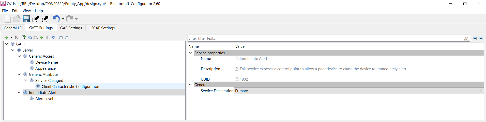
To add the Find Me Target profile, select GATT Settings Tab, click GATT profile (in Figure 21), and then click the + icon(Add Profile). Select the profile from the drop-down menu, as shown in Figure 22.
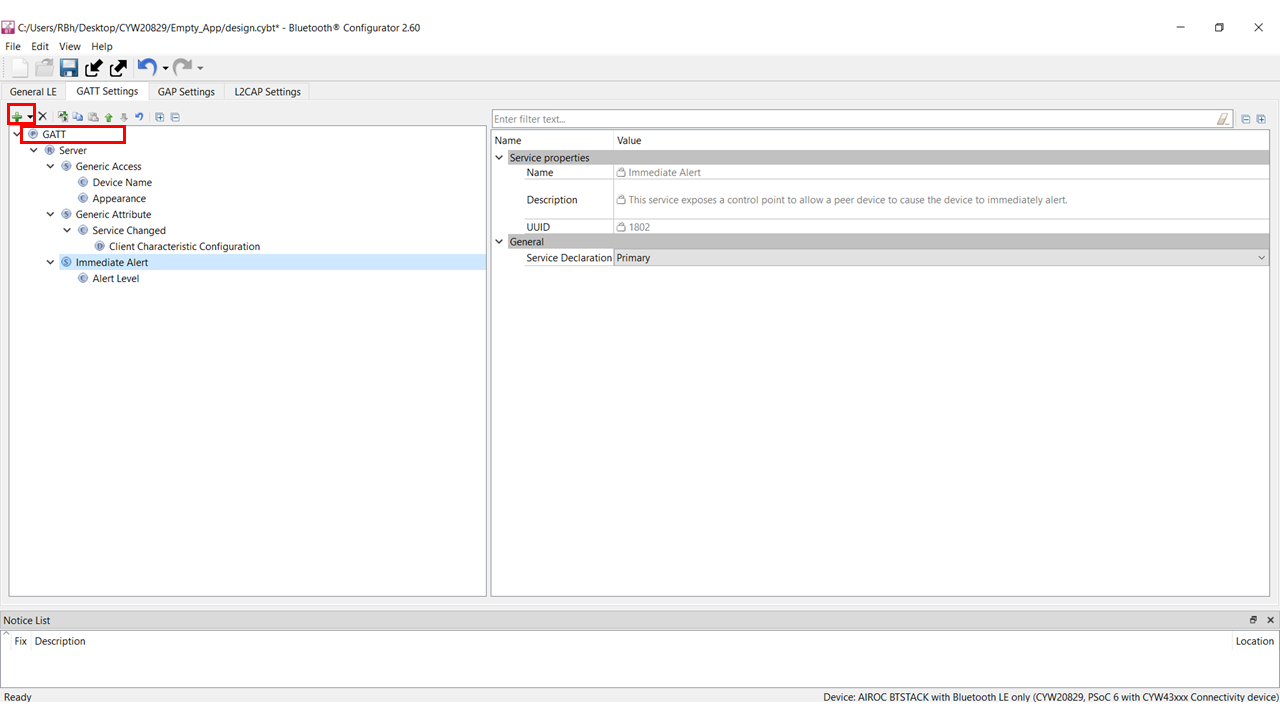
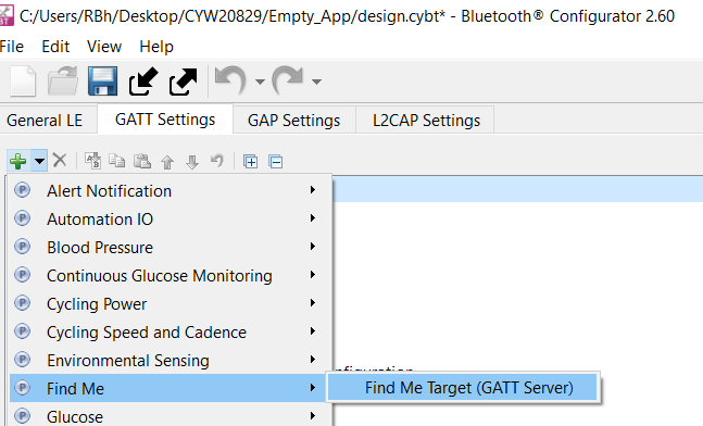
Figure 23 shows the GATT database view after the Find Me Target Server has been added. Note that the Immediate Alert Service corresponding to the Find Me Target profile has been added. Click in the Configurator window or click the Save icon. The configurator stores the GATT database in the source files cycfg_gatt_db.c and cycfg_gatt_db.h in the GeneratedSource folder. The design.cybt file contains the Bluetooth® configurator settings in XML format, which the configurator uses to load the settings when launched again.
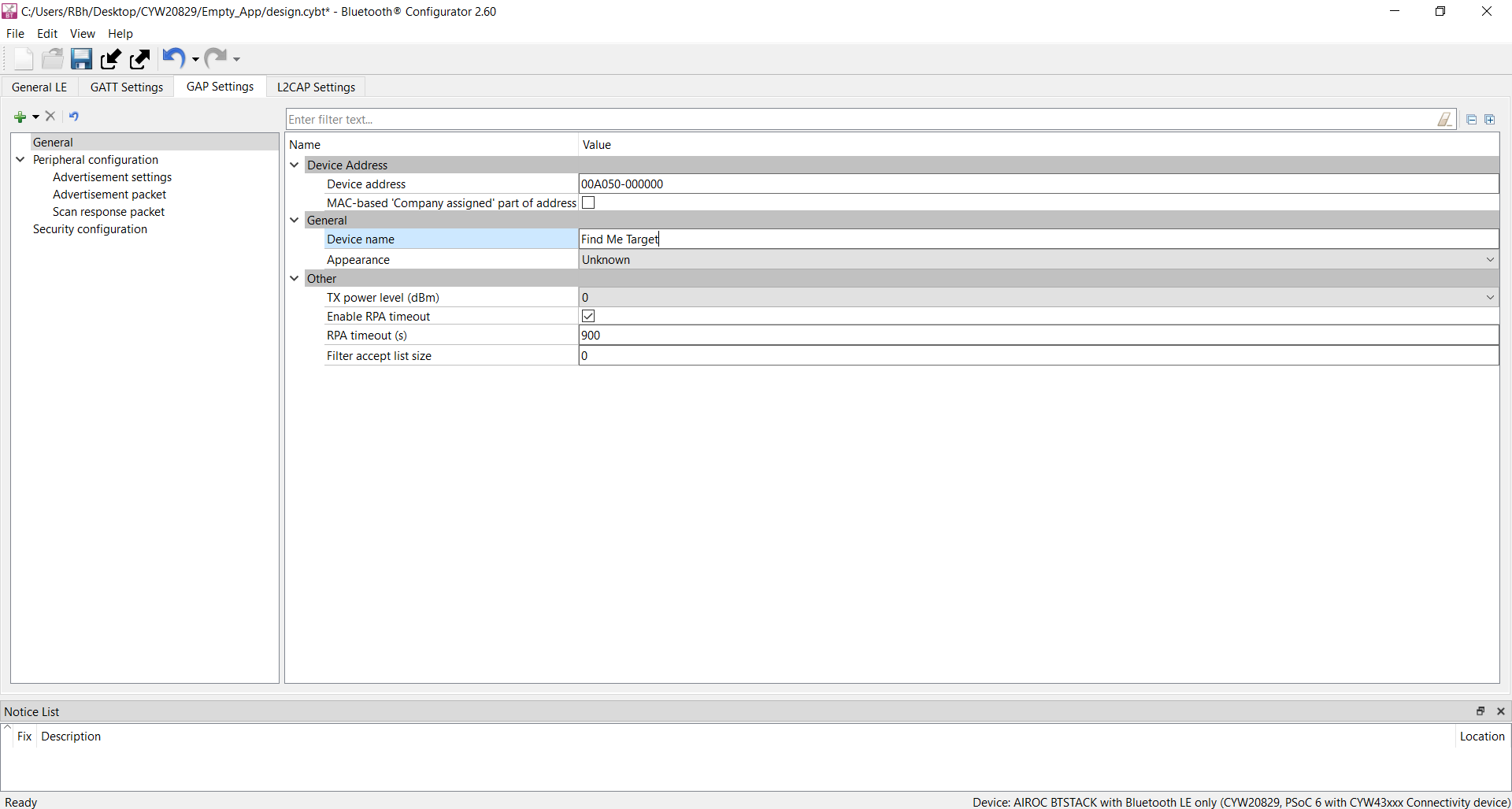
There is a series of panels to cover GAP settings. The left menu provides access to all the panels (see Figure 24).
- Click the GAP Settings tab to display GAP options. The General panel appears by default
- Enter Find Me Target as the device name
All other general settings use default values. This configures the device name that appears when a Host device attempts to discover your device.
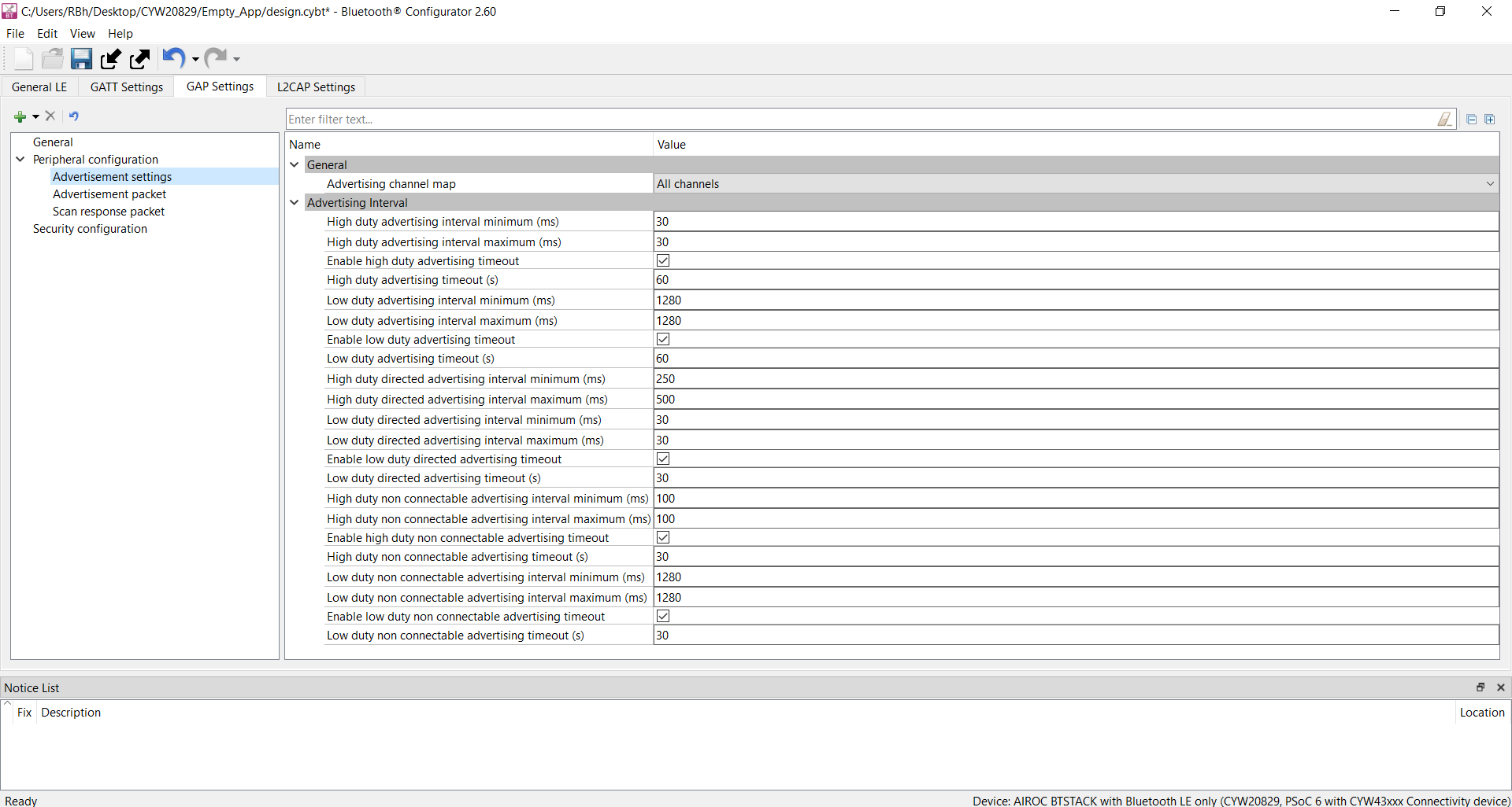
Specify the GAP advertisement settings
- Click the Advertisement settings item in the left menu. Default values work for this application (see Figure 25). It uses a high-duty advertising interval of 30 ms and a low-duty advertising interval of 60 ms. High-duty advertising allows quick discovery and connection but consumes more power because of increased RF advertisement packets
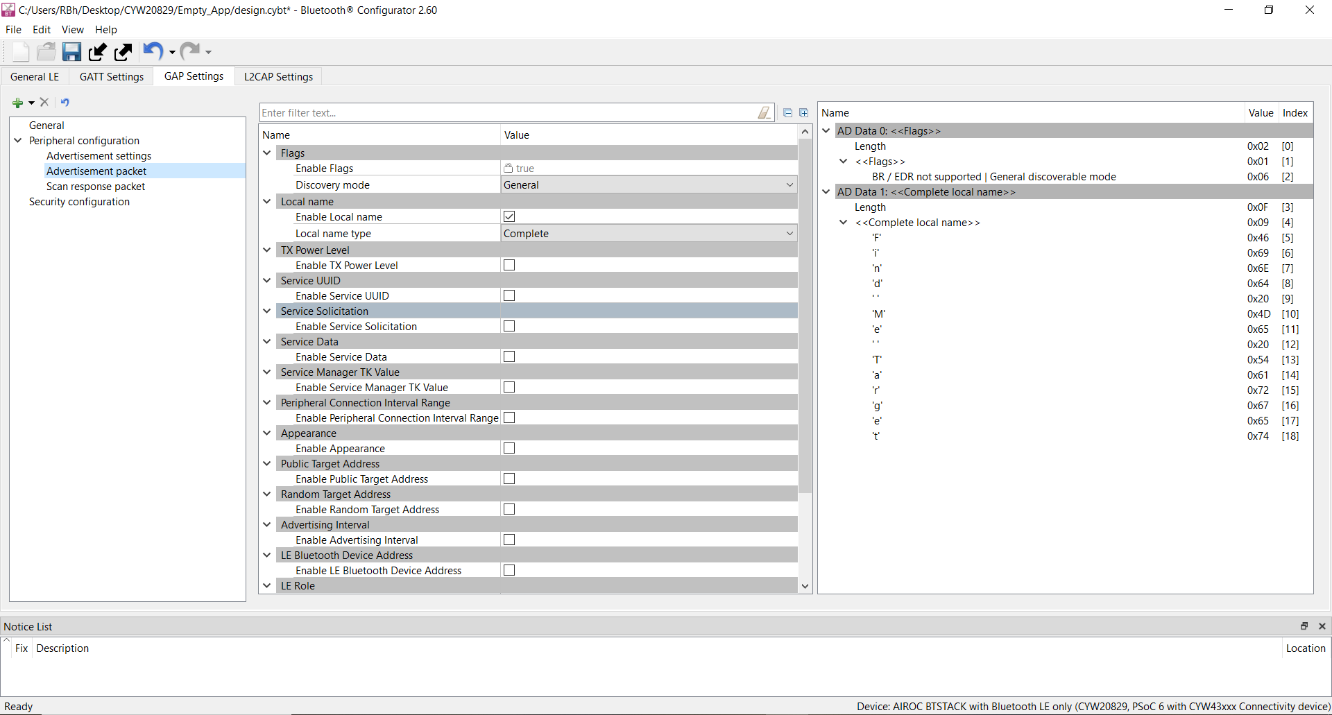
Specify the GAP advertisement packet settings
In this step, you specify the data for the advertisement packet(see Figure 26).
- Click the Advertisement packet item in the left menu, displays the panel
- The application uses a General discovery mode
- Select Enable Local name to include that in the advertisement packet and local name type as Complete
This configures the advertisement packet of the device. As you add items, the structure and content of the advertisement packet appear to the right of the configuration panel.
Specify the scan response packet settings
In this step, you specify the data for the scan response packet (see Figure 27). Note that as you add values, the structure, and content of the scan response packet appear to the right of the configuration panel.
- Click the Scan response packet item in the left menu and the panel appears
- Select Enable Service UUID to include that item in the response. It displays the available UUIDs. Select Immediate Alert
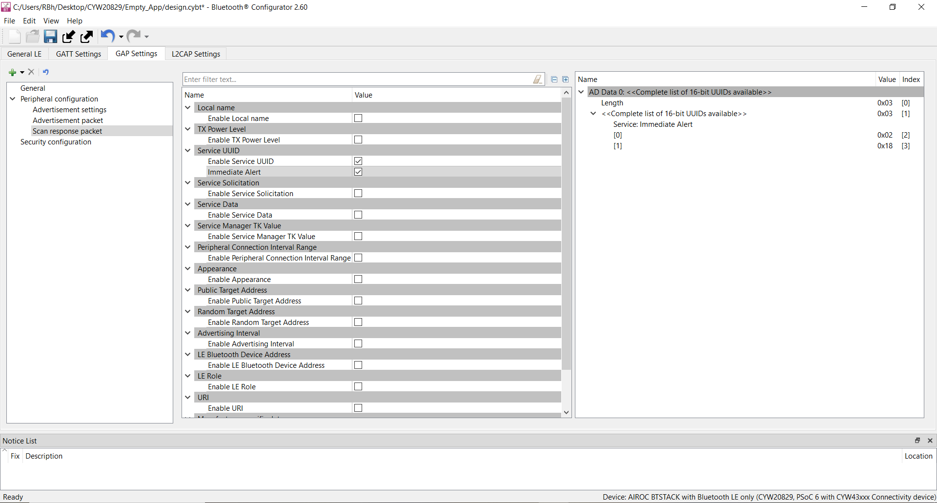
You have now completed the required Bluetooth® settings for the application. Save your settings and close the BT-configurator.
Part 3: Write the application code
At this point in the development process, you have created an application, configured the hardware resources, and generated the configuration code, including the Bluetooth® Low Energy GATT database. This part examines the application code that implements the Find Me Target functionality.
| Path | “Using CE directly” path(Evaluate existing code example (CE) directly) | “Working from scratch” path(Use existing code example (CE) as reference only) |
|---|---|---|
Actions |
Ignore Step 1 - the CE already has all the necessary source files added. Read through the Firmware description section to understand the firmware design. |
Perform Step 1. Read through the Firmware description section to understand the firmware design. |
The application code must do the significant tasks as follows:
- Perform system initialization, including the Bluetooth® stack
- Implement Bluetooth® stack event handler functions for different events, such as an advertisement, connection, and attribute read/write requests
- Implement user interface logic to update the LED state on the kit based on the events triggered
- Add files to your project (required only for the “Working from scratch” flow)
- Locate the mtb-example-btstack-freertos-findme code example that you downloaded from the repository.
- Copy the following files/folder from the
mtb-example-btstack-freertos-findme code example
top-level folder to your mtb-example-btstack-freertos-findme
folder inside the ModusToolbox™ workspace folder
main.capp_bt_utils.capp_bt_utils.hMakefileconfigs folder
- Edit the variable APPNAME in Makefile. Change it to mtb-example-empty-app from mtb-example-btstack-freertos-findme
Firmware description
This section explains the application firmware of the Find Me application. Table 7 lists the important source files relevant to the user application-level code to this code example.
| File name | Comments |
|---|---|
|
cycfg_gatt_db.c, cycfg_gatt_db.h |
These files reside in the GeneratedSource folder under the application folder. They contain the GATT database information generated using the Bluetooth® Configurator tool. |
app_bt_utils.c app_bt_utils.h |
These files consist of the utility functions that will help to debug and develop the applications easier with much more meaningful information. |
|
main.c |
Contains the |
|
design.cybt |
This file is used by the application to specify Bluetooth® configurations and the GATT database using the GUI tool Bluetooth®-configurator. |
|
Configs/COMPONENT_CM33/FreeRTOSConfig.h |
This file is provided by the FreeRTOS library and copied into the application directory. This file has settings for the FreeRTOS kernel. The application can modify the settings based on the use case. |
|
Makefile |
This file contains settings for application build. Add two components FREERTOS and WICED_BLE to include files from FreeRTOS and BTSTACK library for the build. |
Bluetooth® Low Energy GATT database
The cycfg_gatt_db.c and cycfg_gatt_db.h files contain the Bluetooth® Low Energy GATT database definitions for the Find Me Target profile generated in the previous step using the Bluetooth® Configurator tool. The GATT database is accessed by both the Bluetooth® stack and the application code. The stack will directly access the attribute handles, UUIDs, and attribute permissions to process some of the Bluetooth® events. The application code will access the GATT database to perform attribute read/write operations. The relevant database structures are listed as follows.
gatt_database []: This array contains the attribute handles, types, and permissions. Note that this array does not have the actual attribute values, it is maintained as a separate array as followsGATT Value Arrays: The actual GATT database containing the attribute values are declared as a series ofuint8_tarrays under the sectionGATT Initial Value Arraysin cycfg_gatt_db.c. These arrays are also exposed as extern variables for application code access in the cycfg_gatt_db.h file. The FMP target application has these arrays defined by the name’sapp_gap_device_name [],app_gap_appearance [], andapp_ias_alert_level [].app_ias_alert_level []is the Alert Level characteristic corresponding to the IAS service that the client will write to set the alert level. The application code performs the actual write to this attributeapp_gatt_db_ext_attr_tbl []: This array of structures is a GATT lookup table that conveys the mapping of the attribute handles defined ingatt_database []to the GATT value arrays. The application code uses this lookup table to perform the attribute read/write operations on the actual GATT arrays
Bluetooth® stack configuration parameters
The cycfg_bt_settings.c and cycfg_bt_settings.h files contain the runtime
Bluetooth® stack configuration parameters such as
device name (BT_LOCAL_NAME) and core stack configuration
parameters (wiced_bt_cfg_settings []). In the scope of this
application note, will not be covering these parameters. However, you can see the comments
in the source files to learn more about these parameters. Note that the device name defined
in the BT_LOCAL_NAME variable is the one that will be used
on the peer device side to identify the device to establish a connection (“Find Me Target”
in this case).
User application code entry
The main.c file contains the int main () function. This function is the
entry point for executing the user application code after device initialization is
complete. In this code example, this function does the following:
- Initializes the BSP, which includes initializing the target hardware. For example, it initializes system power management and device configuration. It performs other platform-specific initialization. If the BSP initialization fails, the app enters CY_ASSERT. If you are debugging your application, then CY_ASSERT acts as a breakpoint
- Initializes retarget-io to use the debug UART port to view the trace
messages and prints a startup message on the debug UART using the
printffunction - Initializes porting layer required for Bluetooth® communication
between host and controller. The application needs to pass the HCI transport settings
defined in the structure of type
cybt_platform_config_t - Registers a Bluetooth® stack management callback function by
calling
wiced_bt_stack_init (). The stack management callback function then typically controls the rest of the application based on Bluetooth® events. Typically, only a minimal application initialization is done in theint main ()function. Most application initialization is done in the stack callback function once the Bluetooth® stack has been enabled. The stack callback functionapp_bt_management_callbackis defined in main.c. A callback function is a function that is called by another function when a particular event happens. If the stack initialization fails, the application enters CY_ASSERT - Once all the previous steps are initialized successfully, the application starts the FreeRTOS scheduler
Bluetooth® stack events
The main.c file contains the application code logic to handle the different types of events generated by the stack. At a high level, two categories of events need to be handled:
Bluetooth® stack management events
The callback function app_bt_management_callback handles events such as
Stack Enabled, Advertisement State Change, and Security-related events such as Pairing, and
Key Exchange. This callback function is registered as a part of the
int main () function. See the wiced_bt_management_evt_t
definition in wiced_bt_dev.h for the list of management events. It is not required for the
application code to handle all the management events. The events handled depend on the
application requirements. Figure 28 shows the execution logic for the stack management event handler in this code
example.
Figure 28 shows that only three
management events (BTM_ENABLED_EVT, BTM_BLE_ADVERT_STATE_CHANGED_EVT, and
BTM_BLE_CONNECTION_PARAM_UPDATE) are handled in the stack management
callback function.
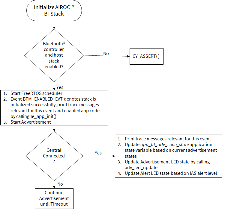
At this point, it is pertinent to discuss the BTM_ENABLED_EVT event, which
is an essential management event that must be handled in all CYW20829 Bluetooth® LE-based applications. It signifies that the Bluetooth® stack has been enabled. All the application code initialization is done
only after the Bluetooth® stack has been enabled successfully by
calling the le_app_init() function as Figure 28 shows.
The le_app_init () function, defined in main.c, performs the
initialization tasks listed below. For any CYW20829 Bluetooth®
LE-based application that you create, you should add the required initialization code in
this function.
- Initializes two or one PWM blocks used to control IAS LED and Advertisement LED. On BSP CYW920829M2EVK-02, two LEDs are available on the board, therefore, two PWMs are initialized
- Disables pairing by calling
wiced_bt_set_pairable_mode (). For this application, the pairing feature is not used - Configures the advertisement packet data by calling
wiced_bt_ble_set_raw_advertisement_data (). Look at this function definition in the code example to understand how to configure the elements of an advertisement packet - Registers the callback function to handle GATT events
(
le_app_gatt_event_callback ()) by callingwiced_bt_gatt_register () - Initializes the GATT database (
gatt_database) defined in cycfg_gatt_db.c by callingwiced_bt_gatt_db_init () - As the final step of the initialization process, the device starts advertising by
calling
wiced_bt_start_advertisements ()
GATT events
The le_app_gatt_event_callback () function handles GATT events such as
connection and attribute request events. This function is registered with a call to
wiced_bt_gatt_register () from the le_app_init ()
function. See the wiced_bt_gatt_evt_t definition in wiced_bt_gatt.h
for the list of GATT events. It is not required for the application code to handle all the
GATT events. The events handled depend on the application requirements. Figure 29 shows the execution logic
for the GATT event handler in this code example. Figure 29 shows that only two GATT
events (GATT_CONNECTION_STATUS_EVT and
GATT_ATTRIBUTE_REQUEST_EVT) are handled in the function.
At this point, it is relevant to discuss the GATT_ATTRIBUTE_REQUEST_EVT
event, which is used to process the GATT Attribute read/write operations. Figure 30 gives information on the
functions called in the case of a read or write operation. In this code example, when the
Find Me Locator updates the IAS Alert Level characteristic on the CYW20829 Bluetooth® LE device, GATT_ATTRIBUTE_REQUEST_EVT is triggered,
which in turn calls the series of functions related to the attribute write request. At the
end of the write operation, the app_ias_alert_level [] function in the
GATT database in cycfg_gatt_db.c gets updated with the alert level set by the Find
Me Locator, and the LED is set appropriately to the alert level.
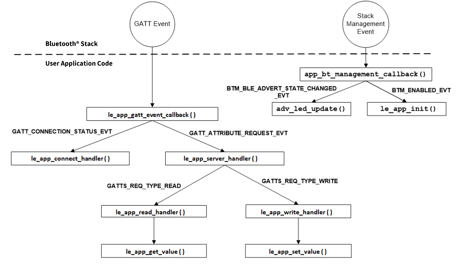
Figure 30 shows the function call chart summarizing the sequence of
function calls for different stack events for this application. All these functions (except
adv_led_update ()) are defined in main.c. Refer to the source code to understand the implementation details of these
functions.
User interface logic
The design uses two LEDs for the user interface, whose details are as follows:
- USER LED1 (red LED) on the kit indicates the advertising/connected state of the Bluetooth® Low Energy peripheral device. USER LED1 is in the OFF
state when the device is not advertising, blinking state while advertising, and always
in the ON state when connected to the peer device. See the
adv_led_update ()function for implementation details. A global state variableapp_bt_adv_conn_stateis used to update the LED state. Theadv_led_update ()function is called from two places in the application code:- The
app_bt_management_callback ()function updates USER LED1 when the advertisement state changes (stack management eventBTM_BLE_ADVERT_STATE_CHANGED_EVT) - The
le_app_connect_handler ()function updates USER LED1 when the connection state changes (GATT eventGATT_CONNECTION_STATUS_EVT)
- The
- USER LED2 (orange LED) on the kit indicates the IAS alert level characteristic when the
device is connected to a peer device. When connected to a peer device, USER LED2 is in
the OFF state for low alert, blinking state for mid alert, and ON state for high alert.
When the device is not connected to any peer device, USER LED2 is in the ON state. See
the
ias_led_update ()function for implementation details. Theias_led_update ()function is called from two places in the application code:- The
le_app_set_value ()function updates USER LED2 when an attribute write request to the IAS Alert Level characteristic is done from the client side - The
le_app_connect_handler()function drives USER LED2 to the OFF state when a disconnection occurs (GATT eventGATT_CONNECTION_STATUS_EVT)
- The
Part 4: Build, program, and test your design
This section shows how to build the application and program the CYW20829 MCU on the CYW20829 EVK's. It also explains how to test the Find Me Profile Bluetooth® Low Energy design using the AIROC™ Bluetooth® Connect mobile app, and the USB – UART serial interface to view the Bluetooth® stack and application trace messages.
At this point, it assumes that you have followed the previous steps in this application note to develop the Find Me Profile application.
| Path | “Using CE directly” path(Evaluate existing Code Example (CE) directly) | “Working from scratch” path(Use existing Code Example (CE) as reference only) |
|---|---|---|
|
Actions |
Perform all the steps in this section |
Perform all the steps in this section |
Connect the kit to your PC using the provided USB cable.
- The USB – UART serial interface on the kit provides access to the UART
interface of the CYW20829 EVK's. Use your favorite serial terminal application and
connect to the USB – UART serial port. Configure the terminal application to access the
serial port using the following settings:
Baud rate: 115200 bps; Data: 8 bits; Parity: None; Stop: 1 bit; Flow control – None; New line for receiving data: Line Feed (LF) or auto setting
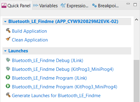
- Build and program the application: In the project explorer, select the <App Name>_LE_Findme project. In the Quick Panel, scroll to the Launches section, and click the <App Name> Program(KitProg3_MiniProg4) configuration as shown in Figure 31.
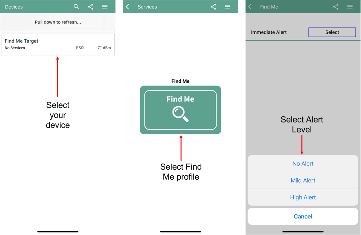
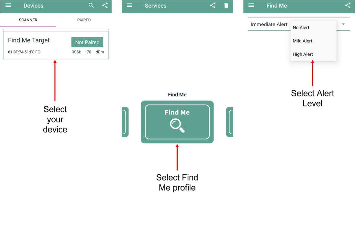
- To test using the AIROC™
Bluetooth® Connect mobile app, follow these steps
(see equivalent AIROC™
Bluetooth® Connect app screenshots in Figure 32 for iOS
and Figure 33
for Android.
- Turn ON Bluetooth® on your Android or iOS device
- Launch the AIROC™ Bluetooth® Connect app
- Press the reset switch on the CYW20829 EVK's to start sending advertisements. The Red LED (USER LED1) starts blinking to indicate that advertising has begun. Advertising will stop after 120 seconds if a connection has not been established
- Swipe down on the AIROC™ Bluetooth® Connect app home screen to start scanning for Bluetooth® Low Energy peripherals; your device appears on the AIROC™ Bluetooth® Connect app home screen. Select your device to establish a Bluetooth® Low Energy connection. Once the connection is established, the Red LED (USER LED1) changes from a blinking state to the always ON state
- Select the 'Find Me' Profile from the carousel view (swipe left or right to rotate the carousel)
- Select an Alert Level value on the Find Me Profile screen. Observe that the state of the Orange LED (USER LED2) on the device changes based on the alert level
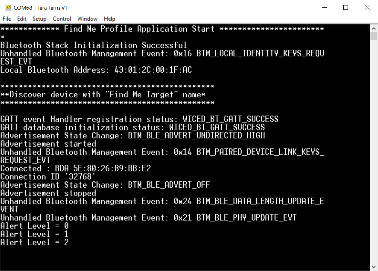
- Use the USB – UART serial port to view the Bluetooth® stack and application trace messages in the terminal window as shown in Figure 34.
Now, you have successfully developed a simple Bluetooth® Low Energy application for the CYW20829 device using Eclipse IDE for ModusToolbox™. For further learning about the CYW20829 device including technical documents, additional code examples, see the References section.
Summary
This application note explored the CYW20829 Bluetooth® MCU device architecture, the associated development tools, and the steps to create a simple Bluetooth® Low Energy application for CYW20829 EVK's using ModusToolbox™. CYW20829 Bluetooth® LE is a Bluetooth® 5.4-compliant, standalone baseband processor with an integrated 2.4-GHz transceiver with support for Bluetooth® Low Energy. The device is intended for use in audio (source), sensors (medical, home, and security), HID, and remote-control functionality as well as a host of other IoT applications.
A wealth of code examples, application notes, and other technical documents are available to help you quickly develop CYW20829-based Bluetooth® applications that meet your end application requirements. See the References section to continue learning more about the CYW20829 device and develop Bluetooth® applications.
References
-
Device documentation
-
Development kits
-
Code examples
- Code examples for ModusToolbox™ software - Visit this code example for a comprehensive collection of code examples using ModusToolbox™ IDE
-
Tool documentation
-
Tool
- ModusToolbox™ software - The Infineon IDE for IoT designers
Revision history
Trademarks
The Bluetooth® word mark and logos are registered trademarks owned by Bluetooth SIG, Inc., and any use of such marks by Infineon is under license.