About this document
Scope and purpose
This application note describes the PSOC™ 6 MCU, IEC 60730 Class B and IEC 61508 safety integrity level (SIL) safety software library for use with ModusToolbox™. The document includes the safety library source code and example projects for PSOC™ 61x4, 62x4, 61x5, 62x5, 61x6/61x7, 62x6/62x7, 61x8/61xA, and 62x8/62xA device families with self-check routines to help ensure reliable and safe operation. You can integrate the library routines and examples included in the example projects with your application. This application note also describes the API functions that are available in the library.
Intended audience
The intended audiences for this document are design engineers, technicians, and developers of electronic systems.
This document is intended for anyone who uses the PSOC™ 6 software libraries for ModusToolbox™ software.
Introduction
Today, the majority of automatic electronic controls for home appliances and industrial products use single-chip microcontroller units (MCUs). Manufacturers develop real-time embedded firmware that executes in the MCU and provides the hidden intelligence to control home appliances and industrial machines. MCU damage due to overheating, static discharge, overvoltage, or other factors can cause the end product to enter an unknown or unsafe state.
The International Electrotechnical Commission (IEC) 60730-1 safety standard discusses the mechanical, electrical, electronic, environmental endurance, electromagnetic compatibility (EMC), and abnormal operation of home appliances. IEC 61508 details the requirements for electrical/electronic/programmable electronic (E/E/PE) safety-related systems in industrial designs. The test requirements of both specifications are similar and are addressed in this document and the safety software library.
This application note focuses on Annex H of IEC 60730-1, “Requirements for electronic controls”, and Annex A of IEC 61508-2, “Techniques and measures for E/E/PE safety-related systems: control of failures during operation”. These sections detail tests and diagnostic methods that promote the safe operation of embedded control hardware and software for home appliances and industrial machines.
Overview of IEC 60730-1 Annex H
Annex H of the IEC 60730-1 standard classifies appliance software into the following categories:
- Class A control functions, which are not intended to be relied upon for the safety of the equipment. Examples are humidity controls, lighting controls, timers, and switches
- Class B control functions, which are intended to prevent the unsafe operation of controlled equipment. Examples are thermal cutoffs and door locks for laundry equipment
- Class C control functions, which are intended to prevent special hazards (such as an explosion caused by the controlled equipment). Examples are automatic burner controls and thermal cutouts for closed, unvented water heater systems
Large appliance products, such as washing machines, dishwashers, dryers, refrigerators, freezers, and cookers/stoves, tend to fall into Class B. An exception is an appliance that may cause an explosion, such as a gas-fired controlled dryer, which falls into Class C.
The Class B Safety Software Library and the example projects presented in this application note implement the self-test and self-diagnostic methods prescribed in the Class B category. These methods use various measures to detect software-related faults and errors and respond to them. According to the IEC 60730-1 standard, a manufacturer of automatic electronic controls must design its Class B software using one of the following structures:
- Single channel with functional test
- Single channel with periodic self-test
- Dual channel without comparison (see Figure 1)
In the single-channel structure with the functional test, the software is designed using a single CPU to execute the functions as required. The functional test is executed after the application starts to ensure that all the critical features are functioning reliably.
In the single-channel structure with the periodic self-test, the software is designed using a single CPU to execute the functions as required. The periodic tests are embedded in the software, and the self-test occurs periodically while the software is in execution mode. The CPU is expected to check the critical functions of the electronic control regularly, without conflicting with the end application’s operation.
In the dual-channel structure without a comparison, the software is designed using two CPUs to execute the critical functions. Before executing a critical function, both CPUs are required to share that they have completed their corresponding task. For example, when a laundry door lock is released, one CPU stops the motor spinning the drum and the other CPU checks the drum speed to verify that it has stopped, as shown in Figure 1.The dual-channel structure implementation is costlier because two CPUs (or two MCUs) are required. In addition, it is more complex because two devices are needed to regularly communicate with each other. The single-channel structure with the periodic self-test is the most common implementation.
Overview of IEC 61508-2 Annex A
Annex A of IEC 61508-2 defines the maximum diagnostic coverage that may be claimed for relevant techniques and measures in industrial designs. Additional requirements not covered in this library may be applicable to specific industries such as rail, process control, automotive, nuclear, and machinery. For each safety integrity level (SIL), the annex recommends techniques and measures for controlling random hardware, systematic, environmental, and operational failures. More information about architectures and measures is available in Annex B of IEC 61508-6 and Annex A of IEC 61508-7.
To avoid or control such failures when they occur, a number of measures are normally necessary. The requirements in IEC 61508 Annexes A and B are divided into the measures used to avoid failures during the different phases of the E/E/PE system safety life cycle (Annex B) and those used to control failures during operation (Annex A). The measures to control failures are built-in features of the E/E/PE safety-related systems.
The process starts by evaluating the risk for each hazardous event of the controlled equipment. Typically, diagnostic coverage and safe failure fraction are then determined based on the likelihood of each failure occurring, combined with the consequence of the failure. This weighs the risk such that a remote catastrophic failure has a risk similar to a frequent negligible failure, for example. The result of the risk assessment is a target SIL that becomes a requirement for the end system.
- SIL 1: ≥10-6 to < 10-5 (1 failure in 11 years)
- SIL 2: ≥10-7 to < 10-6 (1 failure in 114 years)
- SIL 3: ≥10-8 to < 10-7 (1 failure in 1,144 years)
- SIL 4: ≥10-9 to < 10-8 (1 failure in 11,446 years)
IEC 60730 Class B and IEC 61508 requirements
According to the IEC 60730-1 Class B Annex H Table H.11.12.7 and the IEC 61508-2 Annex A Tables A.1 to A.14, certain components must be tested, depending on the software classification. Generally, each component offers optional measures to verify or test the corresponding component, providing flexibility for manufacturers.
To comply with Class B IEC 60730 and IEC 61508 for single-channel structures, manufacturers of electronic controls are required to test the components listed in Table 1.
| Class B IEC 60730 components required to be tested on electronic controls (Table H.11.12.7 in Annex H) | IEC 61508 components required to be tested (Tables A.1–A14 in Annex A) | Fault/error |
|---|---|---|
| 1.1 CPU registers | A.4, A.10 CPU registers | Stuck at |
| 1.3 CPU program counter | A.4, A.10 Program counter | Stuck at |
| 2. Interrupt handling and execution | A.4 Interrupt handling | No interrupt or too frequent interrupt |
| 3. Clock | A.11 Clock | Wrong frequency |
| 4.1 Invariable memory | A.5 Invariable memory | All single-bit faults |
| 4.2 Variable memory | A.6 Variable memory | DC fault |
| 4.3 Addressing (relevant to variable/invariable memory) | A.4, A.10 Address calculation | Stuck at |
| 5.1 Internal data path data | A.8 Data paths (internal communication) | Stuck at |
| 5.2 Internal data path addressing (for expanded memory MCU systems only) | _ | Wrong address |
| 6.1 External communications data | A.7 I/O units and interface | Hamming distance 3 |
| 6.2 External communications addressing | A.7 I/O units and interface | Hamming distance 3 |
| 6.3 Timing | _ | Wrong point in time/sequence |
| 7.1 I/O periphery | A.7 I/O units and interface | Fault conditions specified in Appendix B, “IEC 60730-1, H.27” |
| 7.2.1 Analog A/D and D/A converters | A.3 Analog signal monitoring | Fault conditions specified in Appendix B, “IEC 60730-1, H.27” |
| 7.2.2 Analog multiplexer | _ | Wrong addressing |
The user application must determine whether interrupts need to be enabled or disabled during the execution of the Class B Safety Software Library. For example, if an interrupt occurs during execution of the CPU self-test routine, an unexpected change may occur in any register. Therefore, when the interrupt service routine (ISR) is executed, the contents of the register will not match the expected value.
The Class B Safety Software Library example projects show where interrupts need to be disabled and enabled for correct self-testing.
Safety library usage
The Safety Software Library described in this application note can be used with PSOC™ 6 MCU devices. The library includes APIs that are designed to maximize application reliability through fault detection. The mtb-stl library is developed with adherence to Class B standards. Infineon provides the mtb-stl middleware and a few code examples in source to customers. See the code examples for PSOC™ 6 MCU on GitHub. The STL and Class B certification of the supported devices component will be a part of enabling the customer to obtain certification for their safety critical system.
Some self-tests can be applied by only adding an appropriate API function to the *.c and *.h files from the Class B Safety Software Library.
This application note describes and implements self-test functions:
- Self-test functions to help meet the IEC 60730-1 Class B standards.
- CPU registers: Test for stuck bits
- Program counter: Test for jumps to the correct address
- Program flow: Test for checking correct firmware program flow
- Interrupt handling and execution: Test for proper interrupt calling and periodicity
- Clock: Test for wrong frequency
- Flash (invariable memory): Test for memory corruption
- SRAM (variable memory): Test for stuck bits and proper memory addressing
- Stack overflow: Test for checking stack overflow with the program data memory during program execution
- Digital I/O: Test for pins short
- Analog-to-digital converter (ADC) and digital-to-analog converter (DAC): Test for proper functionality
- Communications (UART, SPI, I2C, CAN FD): Test for correct data reception
- Additional self-test functions that PSOC™ 6 MCU can support due to programmable interconnect. Often, the
end application also needs these self-tests, even though they are not provided
in Appendix B of IEC 60730-1 or IEC 61508-2.
- Opamp test
- Comparator test
- Start-up configuration registers test
- Watchdog test for chip reset
- CAPSENSE™ test for proper functionality and external/internal hardware damage
All self-tests can be executed once immediately after device startup and continuously during device operation. Performing the self-test at startup provides an opportunity to determine whether the chip is suitable for operation prior to executing the application firmware. Self-tests executed during normal operation allow continuous damage detection and user-defined corrective actions.
The following sections describe the implementation details for each test and list the APIs required to execute the corresponding tests.
API functions for PSOC™ 6 MCU
| Test file name | Test function | Return values |
|---|---|---|
| SelfTest_Analog.c | SelfTest_ADC |
0: No error 1: Error detected |
SelfTests_Opamp |
0: No error 1: Error detected |
|
SelfTests_Comparator |
0: No error 1: Error detected |
|
|
|
0: No error 1: Error detected |
|
| SelfTest_Clock.c | SelfTest_Clock |
1: Test failed 2: Still testing 3: Test completed 4: Incorrect usage |
SelfTest_Clock_ISR_TIMER |
– | |
| SelfTest_ConfigRegisters.c | SelfTests_StartUp_ConfigReg |
0: No error 1: Error detected |
SelfTests_Save_StartUp_ConfigReg |
0: No error 1: Error detected |
|
SelfTests_Init_StartUp_ConfigReg |
– | |
| SelfTest_CPU.c | SelfTest_CPU_Registers |
0: No error 1: Error detected |
SelfTest_PC |
0: No error 1: Error detected |
|
SelfTest_PROGRAM_FLOW |
0: No error 1: Error detected |
|
SelfTest_Flash.c |
SelfTest_FlashCheckSum |
1: Error detected 2: Checksum for one block was calculated, but the end of the flash was not reached 3: Pass, checksum of all flash is calculated and checked |
SelfTest_Flash_init |
None | |
| SelfTest_Interrupt.c | SelfTest_Interrupt |
0: No error 1: Error detected |
| SelfTest_IO.c | SelfTest_IO |
0: No error 1: Error detected (shorts to VCC) 2: Error detected (shorts to GND) |
SelfTest_IO_GetPinError |
PIN number that cause an error |
|
SelfTest_IO_GetPortError |
PORT number that cause an error | |
| SelfTest_RAM.c | SelfTest_SRAM |
0: No error 1: Error detected |
SelfTest_SRAM_Stack |
0: No error 1: Error detected |
|
| SelfTest_Stack.c | SelfTests_Init_Stack_Range |
None |
SelfTests_Stack_Check_Range |
0: No error 1: Error detected |
|
| SelfTest_FPU_Regs.c | SelfTest_FPU_Registers |
0: No error 1: Error detected |
| SelfTest_IPC.c | SelfTest_IPC |
0: No error 1: Error detected |
| SelfTest_WDT.c | SelfTest_WDT |
0: No error 1: Error detected |
| SelfTest_DMAC.c | SelfTest_DMAC |
0: No error 1: Error detected |
| SelfTest_DMA_DW.c | SelfTest_DMA_DW |
0: No error 1: Error detected |
| SelfTest_Timer_Counter.c | SelfTest_Counter_Timer |
0: No error 1: Error detected |
SelfTest_Timer_Counter_init |
0: No error 1: Error detected |
|
| SelfTest_PWM.c | SelfTest_PWM |
0: No error 1 Error detected |
SelfTest_PWM_init |
0: PWM init success 255: PWM init failed |
|
| SelfTest_PWM_GateKill.c | SelfTest_PWM_GateKill |
0: No error 1: Error detected |
| SelfTest_CANFD.c | SelfTest_CANFD |
0: No error 1: Error detected |
| SelfTest_UART_SCB.c | SelfTest_UART_SCB |
1: Test failed 2: Still testing 3: Test completed OK 4: Error, Tx not empty 5: Error, Rx not empty 6: Error, UART is not enabled |
| SelfTest_UART_master_message.c | UartMesMaster_Init |
None |
UartMesMaster_DataProc |
0: No error 1: Error detected |
|
UartMesMaster_State |
0: The last transaction process finished successfully, the received buffer contains a response. The unit is ready to start a new process 1: The last transaction process finished with an error and the unit is ready to start a new process 2: The unit is busy with an active transaction operation |
|
UartMesMaster_GetDataSize |
Received data size in buffer | |
| SelfTest_UART_slave_message.c | UartMesSlave_Init |
None |
UartMesSlave_Respond |
0: No error 1: Error detected |
|
UartMesSlave_State |
0: The last transaction process is finished 1: The unit has received a marker and there is received data in the buffer. The master waits for a response 2: The unit is busy with sending a response |
|
UartMesSlave_GetDataPtr |
Returns a pointer to the received data buffer | |
UartMes_GetDataSize |
Returns data size | |
| SelfTest_SPI_SCB.c | SelfTest_SPI_SCB |
1: Test failed 2: Still testing 3: Test completed 4: Tx not empty 5: Rx not empty |
| SelfTest_I2C_SCB.c | SelfTest_I2C_SCB |
1: Test failed 2: Still testing 3: Test completed OK |
CPU register test
PSOC™ 6 with the Arm® Cortex®-M4 CPU have 32-bit registers. The following registers are included in the CPU test:
- R0 to R12 – General-purpose registers
- R13 – Stack pointer (SP): There are two stack pointers, with only one available at a time. The SP is always 32-bit-word aligned; bits [1:0] are always ignored and considered to be ‘0’
- R14 – Link register: This register stores the return program counter during function calls
- R15 – Program counter: This register can be written to control the program flow
The checkerboard method is implemented for all CPU registers except the program counter.
All other special function registers like the floating point unit (FPU) are not included in the test. The CPU registers test detects stuck-at faults in the CPU registers by using the checkerboard test. This test ensures that the bits in the registers are not stuck at value ‘0’ or ‘1’. It is a nondestructive test that performs the following major tasks:
- The contents of the CPU registers to be tested are saved on the stack before executing the routine
- The registers are tested by successively writing the binary sequences 01010101 followed by 10101010 into the registers, and then reading the values from these registers for verification
- The test returns an error code if the returned values do not match
Function
uint8	SelfTest_CPU_Registers(void)

Returns:
0 	No error
1	Error detected

Located in:
SelfTest_CPU.c
SelfTest_CPU.h
The function
SelfTest_CPU_Registers is called to do
the CPU test.
If an error is detected, the PSOC™ device should not continue to function because its behavior can be unpredictable and therefore potentially unsafe.
Program counter test
PSOC™ 6 Arm® Cortex®-M4 CPU program counter R15 register is part of the CPU register set. To test this register, a checkerboard test is commonly used; the addresses 0x10155555 and 0x100AAAAA must be allocated for this test. 0x10155555 and 0x100AAAAA represent the checkerboard bit patterns. Devices with reduced Flash memory size use an address that fits in the available address range.
The program counter (PC) test implements the functional test defined in Section H.2.16.5 of the IEC 60730 standard. The PC holds the address of the next instruction to be executed. The test performs the following major tasks:
- The functions that are in flash memory at different addresses are called. For
PSOC™ 6 device, this can be done by using
the linker script in an *.ldfile (for GCC_ARM
compiler).
NV_CONFIG2 0x10155554 :
    {
		. = 0x00;
		KEEP (*(PC5555))
	} >flash =0

NV_CONFIG3 0x100AAAA8 :
	{
		. = 0x00;
		KEEP (*(PCAAAA))

	} >flash =0
In the example project, it is already added to the custom linker.ld file shipped with the example project
- The functions return a unique value
- The returned value is verified using the PC test function
- If the values match, the PC branches to the correct location, or a watchdog timer (WDT) triggers a reset because the program execution is out of range
Function
uint8	SelfTest_PC(void)
Returns:	0 	No error
            1	 Error detected
Located in: SelfTest_CPU.c
			SelfTest_CPU.h
The function
SelfTest_PC() is called to do the PC
test.
Program flow test
A specific method is used to check program execution flow. For every critical execution code block, unique numbers are added to or subtracted from complementary counters before block execution and immediately after execution. These procedures allow you to see if the code block is correctly called from the main program flow and to check if the block is correctly executed.
As long as there are always the same number of exit and entry points, the counter pair will always be complementary after each tested block. See Figure 2.
Function
uint8_t SelfTest_PROGRAM_FLOW(void)

Returns:
0 	No error
1	Error detected

Located in:
SelfTest_CPU.c
SelfTest_CPU.h
Interrupt handling and execution test
The PSOC™ 6 device interrupt controllers provide the mechanism for hardware resources to change the program address to a new location independent of the current execution in main code. They also handle continuation of the interrupted code after completion of the ISR.
The interrupt test implements the independent time-slot monitoring defined in Section H.2.18.10.4 of the IEC 60730 standard. It checks whether the number of interrupts that occurred is within the predefined range.
The goal of the interrupt test is to verify that interrupts occur regularly. The test checks the interrupt controller by using the interrupt source driven by the timer module.
Function
uint8	SelfTest_Interrupt(TCPWM_Type* base, uint32_t cntNum)
Parameters:

base – The pointer to a TCPWM instance
cntNum - The Counter instance number in the selected TCPWM

Returns:
         	0 	No error
                1	Error detected
Located in:	SelfTest_Interrupt.c
		SelfTest_Interrupt.h
The SelfTest_Interrupt()
function is called to check the interrupt controller operation. Calling the function
starts the timers.
Timer_1 is configured to generate 25 interrupts per 1 ms. isr_1 counts the number of interrupts that occurred. If the counted value in isr_1 is ≥ 22 and ≤ 27, then the test is passed. The specific number of interrupts to pass this test is application dependent and can be modified as required.
Clock test
The clock test implements independent time-slot monitoring defined in Section H.2.18.10.4 of the IEC 60730 standard. It verifies the reliability of the internal main oscillator (IMO) system clock, specifically, that the system clock is neither too fast nor too slow within the tolerance of the internal low-speed oscillator (ILO). The 32 kHz ILO clock is accurate to ± 10 percent.
Function
uint8_t SelfTest_Clock(TCPWM_Type* base, uint32_t cntNum)
Parameters:
base – Base address of the UART to test

Returns:
  1 - Test failed
  2 - Still testing
  3 - Test completed
  4 - Incorrect Usage

Located in:
SelfTest_Clock.h
SelfTest_Clock.c
Function
void SelfTest_Clock_ISR_TIMER(void)
Parameters:
void

Returns:
void

Located in:
SelfTest_Clock.h
SelfTest_Clock.c
The clock test uses the 16-bit timer0 integrated into the WDT and clocked by the 32.768 kHz ILO. The WDT timer0 is a continuous up counting 16-bit timer with overflow. The test starts by reading the current count of the timer, then waits 1 ms using a software delay, and finally reads the timer count a second time. The two count values are then subtracted and optionally corrected for the special case of a timer overflow mid test. The measured period (nominally 33 counts) is then tested. If it is within the predefined range, the test is passed. Figure 4 shows the clock self-test flowchart.
Flash (invariable memory) test
PSOC™ 6 devices include an on-chip flash memory ranging from 256 KB to 2 MB. The flash memory is organized in rows, where each row contains 32 columns of 128 bits.
To complete a full diagnostic of the flash memory, a checksum of all used flash needs to be calculated. The current library uses a Fletcher’s 64-bit checksum or 32-bit CRC32. The Fletcher’s 64-bit method was chosen as the default because it maintains sufficient bit error detection and is significantly faster and smaller than CRC-32. Fletcher’s 64-bit algorithm reads a full 32-bit word and usually only performs two additions per read while requiring no ROM lookup table as compared to CRC32.
You can change the checksum method by modifying the FLASH_TEST_MODE macro in the SelfTest_Flash.h file. FLASH_END_ADDR in the SelfTest_Flash.h
file defines the end of flash address that needs to be monitored.
Fletcher checksum method
To complete a full diagnostic of the flash memory, a checksum of all used flash needs to be calculated.
The current library uses a Fletcher’s 64-bit checksum method by default. The Fletcher’s 64-bit method was chosen because it is sufficiently reliable.
You can change the Fletcher’s checksum method to any checksum method, by updating the function SelfTest_FlashCheckSum() located in the SelfTest_Flash.c file.
The proposed checksum flash test reads each ROM or flash location and accumulates the values in a 64-bit variable to calculate a running checksum of the entire flash memory. The actual 64-bit checksum of flash is stored in the last 8 bytes of flash itself. When the test reaches the end of flash minus 8 bytes, it stops. Custom linker files are used to place the checksum in the desired location (see Appendix A: Set checksum in flash (invariable memory) test). The calculated checksum value is then compared with the actual value stored in the last 8 bytes of flash. A mismatch indicates flash failure, and code execution is frozen to avoid trying to execute invalid code.
CySysSFlashWriteUserRow to store
checksum in SFlash, if available.CRC-32 method
The CRC-32 method uses a lookup table (LUT) to speed execution but is slower than the Fletcher's 64-bit method due to the need to read memory at byte boundaries and perform multiple bit operations per read. The CRC32 polynomial chosen is the most common version defined in ISO/IEC/IEEE 802-3 with polynomial 0x04C11DB7 (Reversed = 0xEDB88320). To maintain compatibility with the Fletcher 64-bit storage size, the CRC32 value is stored in the last 4 bytes of the 8 byte reserved flash space.
Programming method
Before starting the test, you need to set the correct precalculated checksum, as described in Appendix A: Set checksum in flash (invariable memory) test.
Function
uint8 SelfTest_FlashCheckSum(uint32_t DoubleWordsToTest)

Parameters:
DoubleWordsToTest - number of 32-bit Double Words of flash to be calculated per each function call.

Returns:
1	Error detected
2	Checksum for one block calculated, but end of Flash was not reached
3	Pass, Checksum of all flash is calculated and checked

Located in:
SelfTest_Flash.c
SelfTest_Flash.h
Function
void SelfTest_Flash_init(uint32_t StartAddressOfFlash, uint32_t EndAddressOfFlash, uint64_t flash_ExpectedCheckSum);

Parameters:
StartAddressOfFlash - Start address of the flash from where the checksum needs to be calculated.
EndAddressOfFlash - End address of the flash till where the checksum needs to be calculated.
flash_ExpectedCheckSum - Expected checksum. Must be stored outside the range of check.

Returns:
none

Located in:
SelfTest_Flash.c
SelfTest_Flash.h
The SelfTest_FlashCheckSum() function is called to perform the flash memory
corruption test using the checksum method. During the call, this function calculates the
checksum for one block of flash. The size of the block can be set using parameters in
the SelfTest_Flash.h file:
/*Set size of one block in Flash test*/
#define FLASH_DOUBLE_WORDS_TO_TEST (512u)
The function must be called multiple times until the entire flash area is tested. Each call to the function will automatically increment to the next test block.
- If the checksum for the block is calculated and the end address of the tested flash is reached, the test returns 0x03
- If the checksum for the block is calculated but the end address of the flash is not reached, the test returns 0x02
- If an error is detected, the test returns 0x01
SRAM (variable memory) test
The variable memory test implements the periodic static memory test defined in Section H.2.19.6 of the IEC 60730 standard. It detects single-bit faults in the variable memory. Variable memory tests can be destructive or nondestructive. Destructive tests destroy the contents of memory during testing, whereas nondestructive tests preserve the memory contents. While the test algorithm used in this library is destructive, it is encapsulated in code that first saves the memory contents before a test and then restores the contents after completion.
The variable memory contains data, which varies during program execution. The RAM memory test is used to determine if any bit of the RAM memory is stuck at ‘1’ or ‘0’. The March memory test and checkerboard test are among the most widely used static memory algorithms to check for DC faults.
The March tests comprise a family of similar tests with slightly different algorithms. The March test variations are denoted by a capital letter and allow tailoring of the test to a specific architecture’s test requirements. The March C test is implemented for the PSOC™ 6 Safety Software Library because it provides better test coverage than the checkerboard algorithm and is the optimal March method for this device. Separate functions are implemented for the “variable SRAM” and “stack SRAM” areas to ensure no data is corrupted during testing.
March C test
March tests perform a finite set of operations on every memory cell in the memory array. The March C test is used to detect the following types of faults in the variable memory:
- Stuck-at fault
- Addressing fault
- Transition fault
- Coupling fault
The test complexity is 11n, where “n” indicates the number of bits in memory, and 11 operations are required to test each location. While this test is normally destructive, Infineon provides the March C test without data corruption by testing only a small block of memory in each test, allowing the block’s contents to be saved and restored.
GALPAT test
GALPAT test is similar to March tests, which perform a finite set of operations on every memory cell in the memory array. The GALPAT tests differs only in the algorithm being used to perform the test.
March C algorithm
The March C- Memory Built-In Self Test (MBIST) algorithm covers the majority of SRAM faults, including addressing faults, stuck-at fault, state transition fault, and various coupling faults.
The algorithm is as follows:
- Duplicates data in the area to be tested as this test is destructive
- Write '0' to the block in ascending order
- Read '0' and write '1' in ascending order
- Read '1' and write '0' in ascending order
- Read '0'
- Read '0' and write '1' in descending order
- Read '1' and write '0' in descending order
- Read '0'
- Copy back the original data function
Function
uint8_t SelfTest_SRAM(stl_sram_test_mode_t type, uint8_t *startAddr, uint32_t size, uint8_t *buffAddr, uint32_t buffSize)
Parameters:

base – Base address of the UART to test

type - The type of RAM test to be run MARCH or GALPAT
startAddr - The pointer to start of the RAM block to be tested.
Size - The size of RAM block to be tested.
buffAddr - The pointer to start of the buffer to be used to store/restore data of RAM block to be tested. If NULL, test would be performed  without store/restore being performed.
buffSize - The size of buffer which is used to store/restore. If buffSize is smaller than size, the test internally loops through the RAM block operating on memory size equal to buffSize in each iteration.

Returns:
0 - Test passed
1 - Test failed

Located in:
SelfTest_RAM.c
SelfTest_RAM.h
Function
uint8_t SelfTest_SRAM_Stack(uint8_t *stackBase, uint32_t stackSize, uint8_t *altStackBase)
Parameters:

stackBase -  The pointer to the Stack Base.
stackSize - The size Stack.
altStackBase - The pointer to start of the RAM area to be used as alternate Stack Base. RAM address from altStackBase to (altStackBase - stackSize) is used to store/restore the Stack under test.
                       The existing content of this area will be destructed and this area must not overlap with the Stack under test.

Returns:
0 - Test passed
1 - Test failed

Located in:
SelfTest_RAM.c
SelfTest_RAM.h
GALPAT algorithm
The algorithm is as follows:
- Duplicates data in the area to be tested as this test is destructive
- Initializes the chosen range of memory uniformly (i.e., all 0 s or all 1 s)
- Tests the first memory cell, then invert and all the remaining cells are inspected to ensure that their contents are correct
- Checks after every read access to one of the remaining cells and the inverted cell
- Repeats this procedure for each cell in the chosen memory range
- Carries a second run with the opposite initialization
- Copy back the original data function
Any difference produces a failure message. It can detect stuck-at faults and direct coupling faults. At the end of this test, the original data is restored to its correct location in memory. The GALPAT test can be run by executing the same SelfTest_SRAM() API with the first parameter type set to '1'.
Test time
The SRAM test can be customized to test the configured number of bytes each time it is called. The block size and frequency that the test is called can be modified. The March C test takes .06 ms per 1 KB in its default configuration.
The stack test can be customized to test a configured number of bytes each time it is called. The block size and frequency that the test is called can be modified. The March C test on the stack takes 2.18 ms for each 4 KB in its default configuration.
Stack overflow test
The stack is a section of RAM used by the CPU to store information temporarily. This information can be data or an address. The CPU needs this storage area since there are only a limited number of registers.
In the PSOC™ 6 device, the stack is located at the end of RAM and grows downward. The stack pointer is 32 bits wide and is decremented with every PUSH instruction and incremented with POP.
The purpose of the stack overflow test is to ensure that the stack does not overlap with the program data memory during program execution. This can occur, for example, if recursive functions are used.
To perform this test, a reserved fixed-memory block at the end of the stack is filled with a predefined pattern, and the test function is periodically called to verify it. If stack overflow occurs, the reserved block will be overwritten with corrupted data bytes, which should be treated as an overflow error.
Function
void SelfTests_Init_Stack_Range(uint16_t* stack_address, uint16_t stack_length, uint8_t stack_pattern_blk_size)

Parameters:
stack_address - The pointer to the stack.
stack_length - The length of the stack.
stack_pattern_blk_size - No of bytes to be used to fill the pattern. Must be 2^n where n=1 to        n=8.

Returns:
 none

Located in:
SelfTest_Stack.c
SelfTest_Stack.h
This function is called once to fill the reserved memory block with a predefined pattern.
Function
uint8_t SelfTests_Stack_Check_Range(uint16_t* stack_address, uint16_t stack_length)

Parameters:
stack_address - The pointer to the stack.
stack_length -  The length of the stack.

Returns:
0 	No error
1	Error detected

Located in:
SelfTest_Stack.c
SelfTest_Stack.h
The pattern can be modified using the macro located in the SelfTest_Stack.h file:
#define STACK_TEST_PATTERN 0x55AAuAnalog tests
Analog tests comprise the ADC, comparator, and opamp test. These tests rely on two fixed reference voltages. Depending on the specific PSOC™ device, the reference voltage can be generated internally or externally with the help of external hardware. It is up to the user to configure the reference voltage and route the voltage to the hardware under test. This provides flexibility for the user and control over internal routing. The AMUX buses are segmented allowing for greater flexibility in normal use.
Generating the reference voltages
Voltage reference can be provided to the device using external hardware or using an internal reference voltage. A possible method could be with the use of a voltage divider between VDDA and GND to generate either 2/3*VDDA or 1/3*VDDA as the reference voltage. These reference voltage can be connected to the pin configured as the analog input pin.
ADC test
The ADC test implements an independent input comparison as defined in Section H.2.18.8 of the IEC 60730 standard. It provides a fault/error control technique with which the inputs/outputs that are designed to be within specified tolerances are compared.
The purpose of the test is to check the SAR ADC analog functions. Each ADC enabled by the test is connected to an internal reference voltage using the programmable analog block. If the measured value is more than the expected value, an error is returned.
Function
uint8_t SelfTests_ADC(void * base, uint32_t channel, int16_t expected_res, int16_t accuracy, uint32_t vbg_channel, bool count_to_mV);

Parameters:

base : SAR ADC base addr
channel : Channel to be acanned
expected_res : If count_to_mV = 1 -> pass expected voltage in mV else pass expected counts
accuracy :  Accuracy in count ANALOG_ADC_ACURACCY
vbg_channel : only used in CAT1C device. Used to convert the count to mV.
count_to_mV : convert the count to mV.

Returns:
0 - No error
1 - Error detected

Located in:
SelfTest_Analog.h
SelfTest_Analog.c
To perform this test, the ADC is configured to scan the passed channel. A predefined (reference) voltage is generated externally and is sampled by the ADC.
The test is a success if the digitalized input voltage value is equal to the required voltage value within the defined accuracy. When the test is a success, the function returns '0'; otherwise, it returns '1'.
Comparator test
If the inputs to the comparators can be connected to the internal reference voltage, one side of each comparator is connected to the internal reference voltage and the other side is connected to ground. The results are checked. The inputs are switched and the result is checked again.
If the inputs cannot be modified via the programmable analog block, the test uses the pull-up and pull-down resistors in the GPIO to conduct a similar test.
Function
SelfTests_Comparator(LPCOMP_Type const* lpcomp_base, cy_en_lpcomp_channel_t lpcomp_channel, uint8_t expected_res)

Parameters:
lpcomp_base - The pointer to a Comparator instance
lpcomp_channel - Configured channel number
expected_res - Expected result (1 or 0)

Returns:
0 No error
1 Error detected

Located in:
SelfTest_Analog.c
SelfTest_Analog.h
Opamp test
The opamp is tested by generating the same output as the input (Unity Gain Buffer) and the result is read by the SAR ADC. If it is as per expected the test passes.
Function
uint8_t SelfTests_Opamp(SAR_Type* sar_base, int16_t expected_res, int16_t accuracy, uint32_t opamp_in_channel, bool count_to_mV);

Parameters:
base : SAR ADC base addr
expected_res : If count_to_mV = 1 -> pass expected voltage in mV else pass expected counts
accuracy :  Accuracy in count ANALOG_ADC_ACURACCY
opamp_in_channel : Channel to be acanned (where the output of OP-AMP is connected)
count_to_mV : convert the count to mV.

Returns:
0 -  No error
1 - Error detected

Located in:
SelfTest_Analog.h
SelfTest_Analog.c
DAC test
Input a value to DAC as input and connect the output of DAC to ADC input. If the difference between DAC input and ADC output is the same, then the DAC engine operation is verified. The input value to the DAC maps to 1.5 V.
Function
uint8_t  SelfTests_DAC(CTDAC_Type* dacBase, SAR_Type* adcBase, uint32_t adcChannel)

Parameters:
dacBase - The pointer to a DAC instance
adcBase - The pointer to a SAR ADC instance
adcChannel - channel number of SAR ADC instance

Returns:
0 - No error
1 - Error detected

Located in:
SelfTest_Analog.h
SelfTest_Analog.c
IPC test
Each device has a few free IPC channels and IPC interrupts that can be mapped to each channel. This function implements the IPC functional test.
Function
uint8_t SelfTest_IPC(void)

Returns:
0 - No error
1 - Error detected

Located in:
SelfTest_IPC.c
SelfTest_IPC.h
This function does:
- Write the message to the channel
- Acquire an IPC channel and specify which IPC interrupts must be notified during the lock event
- In the ISR of that IPC interrupt read the data
- Release the IPC channel from the locked state using the same IPC during the release event
- Similarly, for the same channel use all the free interrupt
- Similarly, take all IPC channels with all IPC interrupts
FPU register test
The FPU registers test detects stuck-at faults in the FPU by using the checkerboard test. This test ensures that the bits in the registers are not stuck at value '0' or '1'.
Function
uint8_t SelfTest_FPU_Registers(void)

Returns:
0 - No error
1 - Error detected

Located in:
SelfTest_FPU_Regs.c
SelfTest_FPU_Regs.h
The SelfTest_FPU_Registers function is called to do the FPU test. If an error is detected, the device should not continue to function because its behavior can be unpredictable and therefore potentially unsafe.
It is a destructive test that performs the following major tasks:
- The registers are tested by performing a write/read/compare test sequence using a checkerboard pattern (0x5555 5555, then 0xaaaa aaaa). These binary sequences are valid floating point values
- The test returns an error code if the returned values do not match
DMA/DW test
The DataWire (DW) and direct memory access (DMA) blocks are tested using the following procedure. Each DW or DMA channel is tested using the same procedure. A few devices can have DMA and a few with DW block.
Function
uint8_t SelfTest_DMA_DW(DW_Type * base, uint32_t channel, cy_stc_dma_descriptor_t * descriptor0, cy_stc_dma_descriptor_t * descriptor1,
                        const cy_stc_dma_descriptor_config_t * des0_config,const cy_stc_dma_descriptor_config_t * des1_config,
                        cy_stc_dma_channel_config_t const * channelConfig, en_trig_output_pdma0_tr_t trigLine);

Parameters:
base - The pointer to the hardware DMA block
channel - A channel number
descriptor0 - This is the descriptor to be associated with the channel (transfer 0's to destination).
descriptor1 - This is the descriptor to be associated with the channel (transfer pattern to destination).
des0_config - This is a configuration structure that has all initialization information for the descriptor.
des1_config - This is a configuration structure that has all initialization information for the descriptor.
channelConfig - The structure that has the initialization information for the channel.
trigLine - The input of the trigger mux.

Returns:
0 - No error
1 - Error detected

Located in:
SelfTest_DMA_DW.c
SelfTest_DMA_DW.h
The DMA/DW test performs the following steps:
- A destination block of size 64 bytes is set to `0' with DW transfers using 16 x 32-bit transfers from a fixed address
- The destination block is verified to be all `0`
- The same destination block is filled with 00 00 ff by using an 8-bit DMA from a fixed address with an increment of 3 and a length of 22 (64+(3-1))/3
- The destination block is verified to contain the correct pattern (shown below
with lowest address
first):
ff0000ff0000ff0000ff0000ff0000ff0000ff0000ff0000…
Start-up configuration registers test
This test describes and shows an example of how to check the start-up configuration registers:
- Test digital clock configuration registers
- Test analog configuration registers (set to default values after start-up)
- Test the GPIO configuration and high-speed I/O matrix (HSIOM) registers
These start-up configuration registers are typically static and are in the cy_device.h file after the design is built. In rare use cases, some of these registers may be dynamically updated. Dynamically updated registers must be excluded from this test. Dynamic registers are instead tested in application with the knowledge of the current correct value.
Two test modes are implemented in the functions:
- Store duplicates of start-up configuration registers in flash memory after device start-up. Periodically, the configuration registers are compared with stored duplicates. Corrupted registers can be restored from flash after checking
- Compare the calculated cyclic redundancy check (CRC) with the CRC previously stored in flash if the CRC status semaphore is set. If the status semaphore is not set, the CRC must be calculated and stored in flash, and the status semaphore must be set
Function
cystatus SelfTests_Save_StartUp_ConfigReg(void)

Returns:
0  write in flash is successful
1  error detected during flash writing

Located in:
SelfTest_ConfigRegisters.c
SelfTest_ConfigRegisters.h
Function
void SelfTests_Init_StartUp_ConfigReg(void)

Returns:
none

Located in:
SelfTest_ConfigRegisters.c
SelfTest_ConfigRegisters.h
This function copies all listed start-up configuration registers into the last row(s) of flash as required by the number of registers to save.
Function
uint8 SelfTests_StartUp_ConfigReg(void)

Returns:
0  No error
1  Error detected

Located in:
SelfTest_ConfigRegisters.c
SelfTest_ConfigRegisters.h
This function checks the listed start-up configuration registers. There are two modes of checking:
- CRC-32 calculation and verification
- You can define the mode using the parameters in the SelfTest_ConfigRegisters.h file:
#define STARTUP_CFG_REGS_MODE               CFG_REGS_CRC_MODE/CFG_REGS_TO_FLASH_MODE

#define CFG_REGS_TO_FLASH_MODE (1u)
This mode stores duplicates of registers in flash and compares registers with
the duplicates. It returns a fail (1) if the values are different. Registers can be
restored in this mode. The SelfTests_Save_StartUp_ConfigReg function is used to store duplicates in
flash. CONF_REG_FIRST_ROW defines the location of the start-up configuration registers
in flash memory and is automatically calculated in the SelfTest_ConfigRegisters.h file.
#define CFG_REGS_CRC_MODE (0u) In this mode, the function calculates a CRC-32 of registers and stores the CRC in flash. Later, function calls recalculate the CRC-32 and compare it with the saved value. It returns a fail (1) if the values are different.
By default, the CRC mode values are stored at the 9th, 7th, and 8th byte locations from the end of the flash. While using alongside the flash test, which uses the last 8 bytes of flash, it is recommended to move the CRC mode values to the 16th, 14th, and 15th byte locations from the end of flash.
You can define custom location for CRC-32 values by updating defines CRC_STARTUP_SEMAPHORE_SHIFT, CRC_STARTUP_LO, and CRC_STARTUP_HI in the SelfTest_ConfigRegisters.h file.
The following are the list of default registers included in the library test.
Clock registers:
- SRSS_WDT_CTL
- SRSS_CLK_PATH_SELECT
- SRSS_CLK_ROOT_SELECT
- SRSS_CLK_SELECT
- SRSS_CLK_TIMER_CTL
- SRSS_CLK_ILO_CONFIG
- SRSS_CLK_OUTPUT_SLOW
- SRSS_CLK_OUTPUT_FAST
- SRSS_CLK_ECO_CONFIG
- SRSS_CLK_PILO_CONFIG
- SRSS_CLK_FLL_CONFIG
- SRSS_CLK_FLL_CONFIG2
- SRSS_CLK_FLL_CONFIG3
- SRSS_CLK_PLL_CONFIG
HSIOM registers:
- HSIOM_PRT_PORT_SEL0(HSIOM_PRT0)
- HSIOM_PRT_PORT_SEL1(HSIOM_PRT0)
- HSIOM_PRT_PORT_SEL0(HSIOM_PRT1)
- HSIOM_PRT_PORT_SEL1(HSIOM_PRT1)
- HSIOM_PRT_PORT_SEL0(HSIOM_PRT2)
- HSIOM_PRT_PORT_SEL1(HSIOM_PRT2)
- HSIOM_PRT_PORT_SEL0(HSIOM_PRT3)
- HSIOM_PRT_PORT_SEL1(HSIOM_PRT3)
- HSIOM_PRT_PORT_SEL0(HSIOM_PRT4)
- HSIOM_PRT_PORT_SEL1(HSIOM_PRT4)
- HSIOM_PRT_PORT_SEL0(HSIOM_PRT5)
- HSIOM_PRT_PORT_SEL1(HSIOM_PRT5)
- HSIOM_PRT_PORT_SEL0(HSIOM_PRT6)
- HSIOM_PRT_PORT_SEL1(HSIOM_PRT6)
- HSIOM_PRT_PORT_SEL0(HSIOM_PRT7)
- HSIOM_PRT_PORT_SEL1(HSIOM_PRT7)
- HSIOM_PRT_PORT_SEL0(HSIOM_PRT8)
- HSIOM_PRT_PORT_SEL1(HSIOM_PRT8)
- HSIOM_PRT_PORT_SEL0(HSIOM_PRT9)
- HSIOM_PRT_PORT_SEL1(HSIOM_PRT9)
- HSIOM_PRT_PORT_SEL0(HSIOM_PRT10)
- HSIOM_PRT_PORT_SEL1(HSIOM_PRT10)
- HSIOM_PRT_PORT_SEL0(HSIOM_PRT11)
- HSIOM_PRT_PORT_SEL1(HSIOM_PRT11)
- HSIOM_PRT_PORT_SEL0(HSIOM_PRT12)
- HSIOM_PRT_PORT_SEL1(HSIOM_PRT12)
- HSIOM_PRT_PORT_SEL0(HSIOM_PRT13)
- HSIOM_PRT_PORT_SEL1(HSIOM_PRT13)
I/O pin registers:
- GPIO_PRT_CFG(GPIO_PRT0)
- GPIO_PRT_CFG(GPIO_PRT1)
- GPIO_PRT_CFG(GPIO_PRT2)
- GPIO_PRT_CFG(GPIO_PRT3)
- GPIO_PRT_CFG(GPIO_PRT4)
- GPIO_PRT_CFG(GPIO_PRT5)
- GPIO_PRT_CFG(GPIO_PRT6)
- GPIO_PRT_CFG(GPIO_PRT7)
- GPIO_PRT_CFG(GPIO_PRT8)
- GPIO_PRT_CFG(GPIO_PRT9)
- GPIO_PRT_CFG(GPIO_PRT10)
- GPIO_PRT_CFG(GPIO_PRT11)
- GPIO_PRT_CFG(GPIO_PRT12)
- GPIO_PRT_CFG(GPIO_PRT13)
Analog routing registers:
- PASS_AREF_AREF_CTRL
Watchdog test
This function implements the watchdog functional test. The function starts the watchdog timer (WDT) and runs an infinite loop. If the WDT works, it generates a reset. After the reset, the function analyzes the reset source. If the watchdog is the source of the reset, the function returns; otherwise, the infinite loop executes.
Function
uint8_t SelfTest_WDT(void)

Returns:
0 - Test passed
1 - Test failed

Located in:
SelfTest_WDT.h
SelfTest_WDT.c
Figure 5 shows the test flowchart.
Digital I/O test
PSOC™ 6 device provides up to 102 programmable GPIO pins. Any GPIO pin can be CAPSENSE™, LCD, analog, or digital. Drive modes, strengths, and slew rates are programmable.
Digital I/Os are arranged into ports, with up to eight pins per port. Some of the I/O pins are multiplexed with special functions (USB, debug port, crystal oscillator). Special functions are enabled using control registers associated with the specific functions.
The test goal is to ensure that I/O pins are not shorted to GND or Vcc. Tests to detect shorts between physically adjacent pins are not included and must be added by the integrator as there are end application integrations, where cannot account for in a general-purpose test.
In normal operating conditions, the pin-to-ground and pin-to-VCC resistances are very high. To detect any shorts, resistance values are compared with the PSOC™ device internal pull-up resistors.
To detect a pin-to-ground short, the pin is configured in the resistive pull-up drive mode. Under normal conditions, the CPU reads a logical one because of the pull-up resistor. If the pin is connected to ground through a small resistance, the input level is recognized as a logical zero.
To detect a sensor-to-VCC short, the sensor pin is configured in the resistive pull-down drive mode. The input level is zero under normal conditions.
Function
uint8 SelfTests_IO(void)

Returns:
0       No error
1	Error detected (Short to VCC)
2	Error detected (Short to GND)

Located in:
SelfTest_IO.c
SelfTest_IO.h
Function
uint8_t SelfTest_IO_GetPinError(void);

Returns:
PIN number that cause an error

Located in:
SelfTest_IO.c
SelfTest_IO.h
Function
uint8_t SelfTest_IO_GetPortError(void)

Returns:
PORT number that cause an error

Located in:
SelfTest_IO.c
SelfTest_IO.h
The function SelfTests_IO() is called to check shorts of the I/O pins to GND or Vcc. The
PintToTest array in the SelfTests_IO() function is used to set the
pins that must be tested.
static const uint8 PinToTest[] =
{
	0b11011111,	/* PORT0 mask */
	0b00111111,	/* PORT1 mask */
	0b11111111,	/* PORT2 mask */
	0b11110011,	/* PORT3 mask */
	0b00000000,	/* PORT4 mask */
};
Each pin is represented by the corresponding bit in the PinToTest table port mask. Pin 0 is represented by the LSB,
and pin 7 by the MSB. If a pin should be tested, a corresponding bit should be set to
‘1’.
TCPWM test
This test demonstrates the use of the Class B Safety Test Library to test the TCPWM resource configured as a timer/counter, PWM, and PWM output Gate Kill in PSOC™ 6 MCUs. It verifies the proper operation and accuracy of these peripherals adhering to the IEC 60730 standards.
Timer/counter test
Timer/counter is used to count clocks (timer) or external events (counter). The test uses the timer function. The test should be run on every safety-critical timer/counter.
Function
void SelfTest_Timer_Counter_init(TCPWM_Type* base, uint32_t cntNum, cy_stc_tcpwm_counter_config_t const *config, IRQn_Type intsrc)

Parameters:

base - The pointer to a TCPWM instance.

cntNum - The Counter instance number in the selected TCPWM.

config - The pointer to configuration structure

intsrc - Interrupt source

Returns:

0 - No error
1 - Error detected

Located in: SelfTest_Timer_Counter.c
                   SelfTest_Timer_Counter.h
Function
uint8_t SelfTest_Counter_Timer()

Returns:

0 - No error
1 - Error detected

Located in: SelfTest_Timer_Counter.c
                   SelfTest_Timer_Counter.h
The Timer/counter is tested using the following procedure:
- Configure the block to timer/counter personality
- Configure the input clock to the CPU clock
- Check that the counter is incrementing
PWM test
The PWM is tested using the following procedure:
- Configure a 16-bit PWM to run at 1/3 duty ON, 2/3 OFF duty cycle with a 1 millisecond period. Start the PWM
- Run the CPU in a loop for 5 milliseconds. Poll the output continuously in the loop. Count the instances of 0 and 1 output
- The test is successful if the off/on ratio is between 15/8 and 17/8. A range is used because the CPU polling loop is asynchronous to the PWM timing
Function
uint8_t SelfTest_PWM(GPIO_PRT_Type *pinbase, uint32_t pinNum)

Parameters:
pinbase - The pointer to a GPIO port instance to which the PWM pin is connected to.
pinNum - The GPIO pin number to which the PWM pin is connected to.

Returns:
0 - No error
1 - Error detected

Located in:
SelfTest_PWM.c
SelfTest_PWM.h
Function
uint8_t SelfTest_PWM_init(TCPWM_Type *base, uint32_t cntNum,
			 cy_stc_tcpwm_pwm_config_t const *config, IRQn_Type  intr_src)

Parameters:
base - The pointer to a TCPWM instance.
cntNum - The Counter instance number in the selected TCPWM.
config - The pointer to configuration structure.
intr_src - Interrupt source

Returns:
0 - PWM init Success
255 - PWM init Failed

Located in:
SelfTest_PWM.c
SelfTest_PWM.h
The test must not drive the PWM output pin.
PWM Gate Kill test
The "Gate Kill" function is used in motor controllers and multi-level power converters. When an overvoltage or current state is detected, the Gate Kill shuts down the output drivers in less than 50 nanoseconds after the overvoltage or overcurrent occurs.
Function
uint8_t SelfTest_PWM_GateKill(TCPWM_Type *base, uint32_t cntNum)

Parameters:
base - The pointer to a TCPWM instance
cntNum - The Counter instance number in the selected TCPWM

Returns:
0 - No error
1 - Error detected

Located in:
SelfTest_PWM_GateKill.c
SelfTest_PWM_GateKill.h
- Configure the Kill mode as Stop on Kill
- The low power comparator output or the voltage range violation of SAR ADC is routed to the Kill signal of TCPWM indicating overvoltage/overcurrent condition if voltage on +ve terminal is > -ve
- If overvoltage or overcurrent condition it will Kill PWM output
- The TCPWM base and CntNum is passed to check whether the counter is stopped or not
- If the counter is not incrementing/decrementing, the PWM output is inactive
CAPSENSE™ test
- Sensor shorts
- External capacitor
- Integrity of CAPSENSE™ configuration data
- Integrity of sensor signal (raw count) and sensor baseline
- VDDA
Communications UART test
This test implements the UART internal data loopback test. The test is a success if the transmitted byte is equal to the received byte and returns 2. Each function call increments the test byte. After 256 function calls, when the test finishes testing all 256 values and they are all a success, the function returns 3. Smart I/O is used for loopback and the UART pins are connected to Smart I/O.
Note that only a few Serial Communication Blocks (SCBs) are routed through Smart I/O. However, this test can still be used with other SCBs if the UART Rx and Tx pins are tied together externally.
Function
uint8	SelfTest_UART_SCB(CySCB_Type* base)

Parameters:
base - pointer to SCB hardware to configure

Returns:
1	test failed
2	still testing
3	test completed OK
4	Error, TX not empty
5	Error, RX not empty
6	Error, UART is not enabled.

Located in:
SelfTest_UART_SCB.h
SelfTest_UART_SCB.c
The input and output terminals switch between the corresponding pins and loop to each
other to provide the internal loopback test by using the UART multiplexer and
demultiplexer. If the receiving or transmitting buffers are not empty before the test,
the test is not executed and returns an ERROR_RX_NOT_EMPTY or
ERROR_TX_NOT_EMPTY status.
The test function saves the component configuration before testing and restores them after the test ends. During the call, the function transmits 1 byte. The transmitted value increments after each function call. The range of test values is from 0x00 to 0xFF.
Communications UART data transfer protocol example
For additional system safety when transferring data between system components, you can use communication protocols with cyclic redundancy checks (CRCs) and packet handling. An example of safety communication follows.
To allow the reserved start of packet marker (STX) value to be transmitted, use a common escape method. When any byte in a packet is equal to STX or ESC, it changes to a 2-byte sequence. If packet byte = ESC, replace it with 2 bytes (ESC, ESC + 1). If any packet byte = STX, then replace it with 2 bytes (ESC, STX + 1). This procedure provides a unique packet start symbol. The ESC byte is always equal to 0x1B. It is not a part of the packet and is always sent before the (packet byte + 1) or (ESC, STX + 1). Table 3 shows the packet field descriptions.
| Name | Length | Value | Description |
|---|---|---|---|
| STX | 1 byte | 0x02 | Unique start of packet marker = 0x02. |
| ADDR | 1 or 2 bytes | 0x00-0xFF except 0x02 | Slave address. If this byte is equal to STX, it changes to a 2-byte sequence: (ESC) + (STX + 1). If this byte is equal to ESC, it changes to a 2-byte sequence: (ESC) + (ESC +1) |
| DL | 1 or 2 bytes | 0x00-0xFF except 0x02 | Data length of packet (without protocol bytes). If this byte is equal to STX, it changes to a 2-byte sequence: (ESC) + (STX + 1). If this byte is equal to ESC, it changes to a 2-byte sequence: (ESC) + (ESC + 1) |
| D0-Dn (data) | 1...510 bytes | 0x00-0xFF except 0x02 | Packet's data. If any byte in the data is equal to STX, it changes to a 2-byte sequence: (ESC) + (STX + 1). If any byte in the data is equal to ESC, it changes to a 2-byte sequence: (ESC) + (ESC + 1) |
| CRCH | 1 or 2 bytes | 0x00-0xFF except 0x02 | MSB of packet CRC. CRC-16 is used. CRC is calculated for all packet bytes from ADDR to the last data byte. CRC is calculated after the ESC changing procedure. If this byte is equal to STX, it changes to a 2-byte sequence: (ESC) + (STX + 1). If this byte is equal to ESC, it changes to a 2-byte sequence: (ESC) + (ESC + 1) |
| CRCL | 1 or 2 bytes | 0x00-0xFF except 0x02 | LSB of packet CRC. CRC-16 is used. CRC is calculated for all packet bytes from ADDR to the last data byte. CRC is calculated after the ESC changing procedure. If this byte is equal to STX, it changes to a 2-byte sequence: (ESC) + (STX + 1). If this byte is equal to ESC, it changes to a 2-byte sequence: (ESC) + (ESC + 1) |
Data delivery control
The communication procedure can be divided into three parts:
- Send request (opposite side receives request)
- Wait for response (opposite side analyzes request)
- Receive response (opposite side sends response)
“Send request” consists of sending the STX, sending the data length and data using the byte changing procedure, calculating the CRC, and sending the CRC.
“Receive response” consists of finding the STX and starting the CRC calculation. If the received address is invalid, the search for the STX byte is repeated. If the address is valid, the data length and data bytes are received. The CRC counter then stops and two CRC bytes are received. These bytes are compared with the calculated CRC value.
After sending a request, the guard timer is started to detect if a response is not received within the timeout period.
PSOC™ 6 MCU implementation
The UART SCB components are used to physically generate the signals. The software CRC-16 calculation is applied to every sent/received byte (except STX and the CRC itself). To detect an unsuccessful packet transaction, the timer is used.
Three interrupts implemented in this project provide a fully interrupt-driven background process:
- The transmit interrupt in the UART is configured for a FIFO not full event to take the new data from the RAM and place it into the Tx buffer, and for a transmit complete event to start or stop the CRC calculation
- The receive interrupt in the UART is configured for a FIFO not empty event to analyze the received data, calculate the CRC, and store the received data into RAM
- The timer interrupt is used to detect the end of an unsuccessful transmission
This software unit is implemented as an interrupt-driven driver. That is, you only starts the process and checks the state of the unit. All operation is done in the background.
Four functions for working with the protocol unit for the master
Function 1
void UartMesMaster_Init(CySCB_Type* uart_base, TCPWM_Type* counter_base,  uint32_t cntNum)

Parameters:
uart_base - The pointer to the master UART SCB instance.
counter_base - The pointer to the master TCPWM instance.
cntNum - The Counter instance number in the selected TCPWM.

Returns:
None

Located in:
SelfTest_UART_master_message.h
SelfTest_UART_master_message.c
This function initializes the UART message unit.
Function 2
uint8 UartMesMaster_DataProc(uint8_t address, uint8_t *txd, uint8_t tlen, uint8_t * rxd, uint8_t rlen)

Parameters:
address - slave address for data transfer
txd - pointer to transmitted data
tlen - size of transmitted data in bytes
rxd - pointer to the buffer where the received data will be stored
rlen - size of received data buffer

Returns:
0 - No error
1 - Error detected

Located in:
SelfTest_UART_master_message.h
SelfTest_UART_master_message.c
This function starts the process of transmitting and receiving messages and returns the result of the process start: 0 = success and 1 = error. An error can occur because the unit is already busy sending a message or a null transmitting length was detected.
Function 3
uint8 UartMesMaster_State(void)

Returns:
0 (UM_COMPLETE) – the last transaction process finished successfully, the received buffer contains a response. The unit is ready to start a new process
1 (UM_ERROR) – the last transaction process finished with an error and the unit is ready to start a new process
2 (UM_BUSY) – the unit is busy with an active transaction operation.

Located in:
SelfTest_UART_master_message.h
SelfTest_UART_master_message.c
This function returns the current state of the UART message unit.
Function 4
uint8 UartMesMaster_GetDataSize(void)

Returns:
Received data size in buffer

Located in:
SelfTest_UART_master_message.h
SelfTest_UART_master_message.c
This function returns the received data size that is stored in the receive buffer. If the unit is busy or the last process generated an error, it returns '0'.
Four functions for working with the protocol unit for the slave
Function 1
This function initializes the UART message unit.
void UartMesSlave_Init(CySCB_Type* uart_base, uint8_t address)

Parameter:
uart_base - The pointer to the slave UART SCB instance.
address: Slave address

Returns:
None

Located in:
SelfTest_UART_slave_message.h
SelfTest_UART_slave_message.c
Function 2
uint8 UartMesSlave_Respond(char * txd, uint8 tlen)

Parameters:
txd: Pointer to the transmitted data (request data)
tlen: Length of the request in bytes

Returns:
0 - No error
1 - Error detected

Located in:
SelfTest_UART_slave_message.h
SelfTest_UART_slave_message.c
This function starts respond. It returns the result of process start. Success is' 0' and error is '1' (the unit has not received a marker).
Function 3
uint8 UartMesSlave_State(void)

Returns:
0 (UM_IDLE) – the last transaction process is finished
1 (UM_PACKREADY) – the unit has received a marker and there is received data in the buffer. The master waits for a response.
2 (UM_RESPOND) – the unit is busy with sending a response.

Located in:
SelfTest_UART_slave_message.h
SelfTest_UART_slave_message.c
This function returns the current state of the UART message unit.
Function 4
uint8 UartMes_GetDataSize(void)

Returns:
returns data size

Located in:
SelfTest_UART_slave_message.h
SelfTest_UART_slave_message.c
This function obtains the received data size that was stored in the receive buffer. If the unit state is not UM_PACKREADY, it returns '0'.
Function 5
uint8 * UartMesSlave_GetDataPtr(void)

Returns:
Returns pointer to received data buffer

Located in:
SelfTest_UART_slave_message.h
SelfTest_UART_slave_message.c
This function obtains a pointer to the received data.
Communications SPI test
This test implements the SPI internal data loopback test. The test is a success if the transmitted byte is equal to the received byte and returns 2. Each function call increments the test byte. After 256 function calls, when the test finishes testing all 256 values and they are all a success, the function returns 3. 256 bytes are tested so that all of the cells in the 256 byte FIFO are used.
The Serial Communication Block (SCB) has a loopback capability that is used to enable this test.
Function
uint8 SelfTest_SPI_SCB (SCB_Type* base)

Parameters:

base – Base address of the UART to test


Returns:

1 – Test failed

2 – still testing

3 – Test completed

4 - TX not empty

5 - RX not empty


Located in: SelfTest_SPI_SCB.c

                   SelfTest_SPI_SCB.h
The input and output terminals switch between the corresponding pins and loop to each other to provide the internal loopback test by using the Smart I/O.
Communications I2C test
This test requires connecting the I2C Master and Slave externally according to Figure 7.
This project uses an I2C Master as component under test (Figure 8). With no modifications, the project can also be used for testing I2C Slave (Figure 9). The end application must have the capability of configuring I2C Master as I2C Multi Master.
- Master periodically sends an I2C data addressing slave [0x08]
- Slave reads the data, complements, and writes to slave read buffer
- Master reads the data from slave and compares it with the complement of data sent in last interaction
Function
uint8 SelfTest_I2C_SCB(CySCB_Type* master_base, cy_stc_scb_i2c_context_t* master_context, CySCB_Type* slave_base, cy_stc_scb_i2c_context_t* slave_context,         uint8_t* slave_read_buf, uint8_t* slave_write_buf)

Parameters:
master_base - The pointer to the master I2C SCB instance.
master_context - The pointer to the master I2C SCB context.
slave_base - The pointer to the slave I2C SCB instance.
slave_context - The pointer to the slave I2C SCB context.
slave_read_buf - The pointer to slave read buffer.
slave_write_buf - The pointer to slave write buffer.

Returns:
1 – Test failed
2 – Still testing
3 – Test completed OK

Located in:
SelfTest_I2C_SCB.c
SelfTest_I2C_SCB.h
I2C Write API - Operation
- Initiates I2C Master transaction to write data to the slave
- Waits for Write transfer completion
- Reads the Slave Write buffer
- Performs 1's complement on the read data
- Writes the complemented data to Slave Read Buffer
I2C Read API - Operation
- Initiates I2C Master transaction to read data from the slave
- Waits for Read transfer completion
- Checks whether the data read is equal to the complement of data written
Communications CAN FD test
The CAN FD block is tested using the loopback capability and the test as follows:
- Enable loopback externally or internally based on the parameter passed
- Configure CAN FD to accept message IDs in the range 0x50 to 0x55 in any of the Rx FIFO (1 or 2)
- Transmit a message with message ID 0x60
- Verify that the Rx FIFO is empty
- Transmit a message with message ID 0x52
- Verify that the message is received correctly in the Rx FIFO
Function
uint8_t SelfTest_CANFD(CANFD_Type *base, uint32_t chan, const cy_stc_canfd_config_t *config, cy_stc_canfd_context_t *context, stl_canfd_test_mode_t test_mode);

Parameters:

base - The pointer to a CAN FD instance. <br>
chan - The CAN FD channel number. <br>
config - The pointer to the CAN FD configuration structure.
context - The pointer to the context structure allocated by the user. The structure is used during the CAN FD operation for internal configuration and data retention. User must not modify anything in this structure.
test_mode - internal : will not drive the pin , external : will drive the external pins along with loopback


Returns:

0 - No error
1 - Error detected

Located in: SelfTest_CANFD.c
                   SelfTest_CANFD.h
If the CAN bus fails to operate, the device should be fail-safe. CAN FD to be tested from IP side with loop back mode.
List of certified libraries
| Library name | Version | GitHub commit |
|---|---|---|
| ModusToolbox™ Safety Test Library | 3.0.0.1518 | e94c79778a10544355fac28f8ff2be90460d589a |
| CAPSENSE™ Middleware Library | 5.0.0.6806 | a4aa9306f7e4323994902f0baf5b1570ffbbfe59 |
Summary
This application note described how to implement diagnostic tests defined by the IEC 60730 and IEC 61508 standard. Incorporation of this standard into the design of white goods and other appliances will add a new level of safety for consumers.
By taking advantage of the unique hardware configurability offered by PSOC™ 6 MCU, designers can comply with regulations while maintaining or reducing electronic systems cost. Use of PSOC™ device and the Safety Software Library enables the creation of a strong system-level development platform to achieve superior performance, fast time to market, and energy efficiency.
Appendix A: Set checksum in flash (invariable memory) test
The following instructions will help you program your part for proper flash and ROM diagnostic testing.
-
Build a project in ModusToolbox™ and store the checksum value set to 0x0000 in the source file.
For the GCC compiler:#if defined(__GNUC__) /* Allocate last 8 bytes in Flash for flash checksum for PSoC6 */ static volatile const uint64_t flash_StoredCheckSum __attribute__((used, section(".flash_checksum"))) = 0x0000000000000000ULL; #endif - Read the calculated flash checksum. There are two ways:
- Read the checksum in debug mode
- Open the project file SelfTest_Flash.c file and
set the breakpoint in debug mode to the line shown in Figure 10
Figure 10. Stored checksum in debug mode 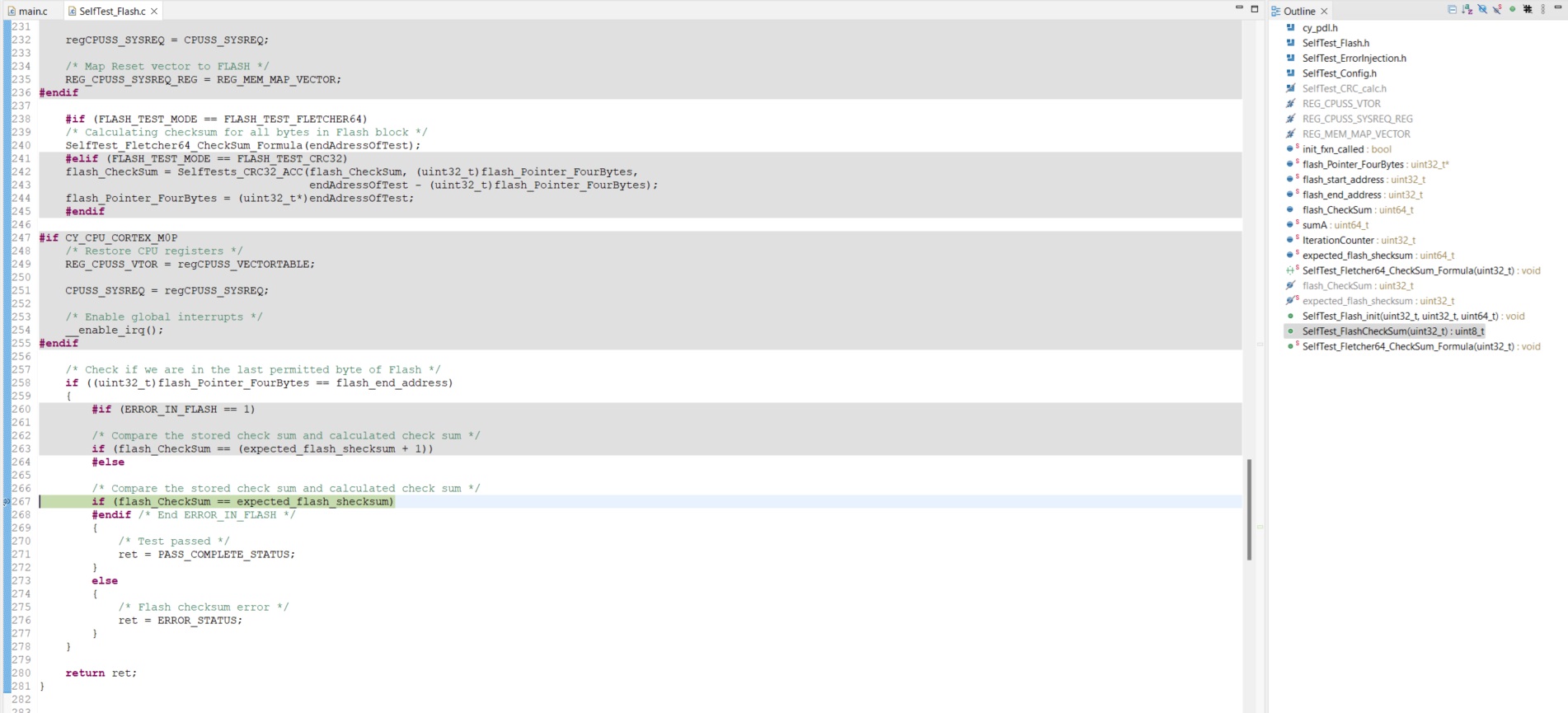
- Press [F10] to single step past the breakpoint location and hover the
mouse over the
flash_CheckSumvariable. A value stored in this variable should appear, as shown in Figure 11.Figure 11. Retrieve the stored checksum value in debug mode 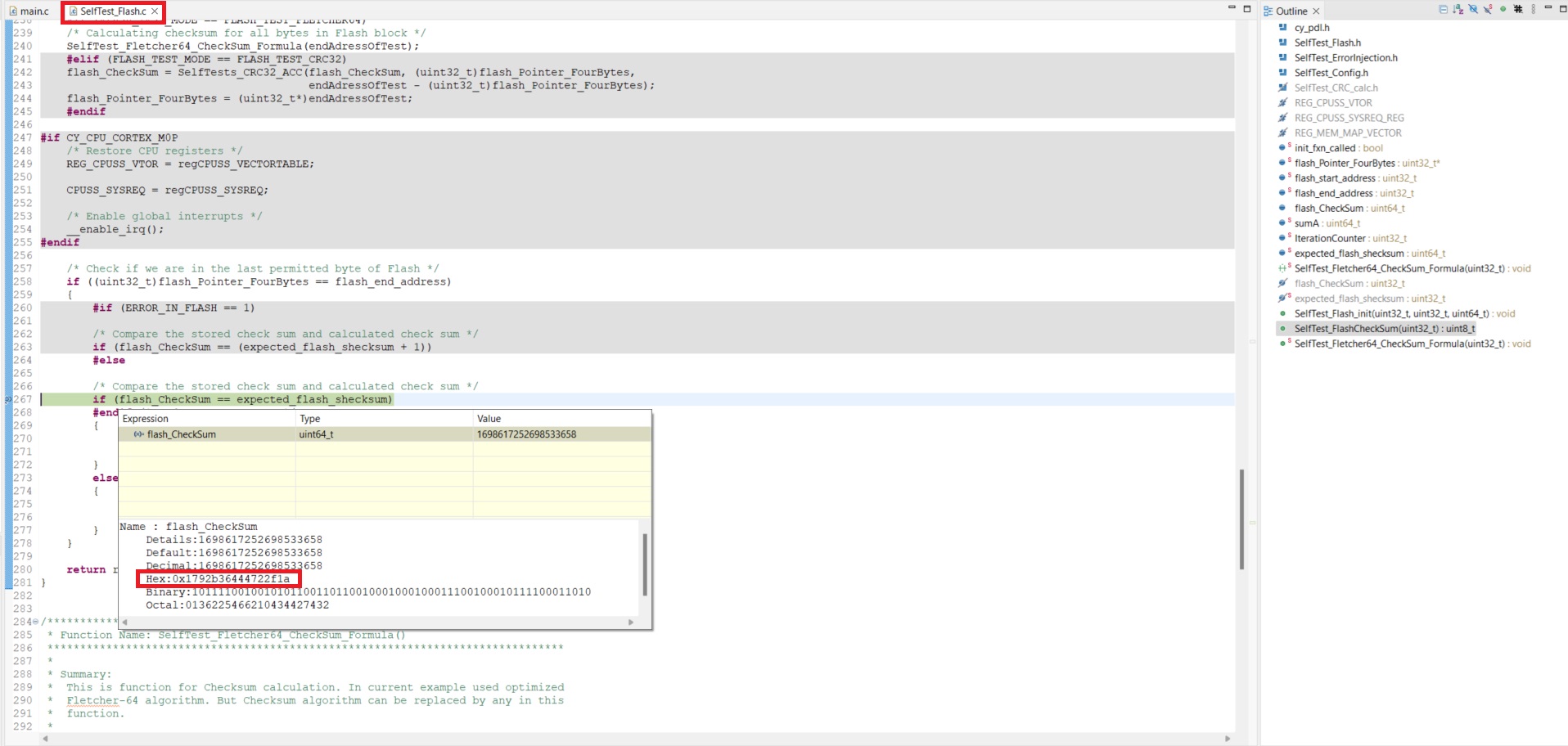
- Open the project file SelfTest_Flash.c file and
set the breakpoint in debug mode to the line shown in Figure 10
- Read the checksum using the communication protocol:
- To speed up the process of testing the flash checksum outputs, use a
UART. This feature is implemented in Class B firmware. It will print
the calculated checksum value when the stored flash checksum does
not match the calculated flash checksum. To use this project, set
the UART parameters shown in Figure 12.
Figure 12. Checksum output using UART 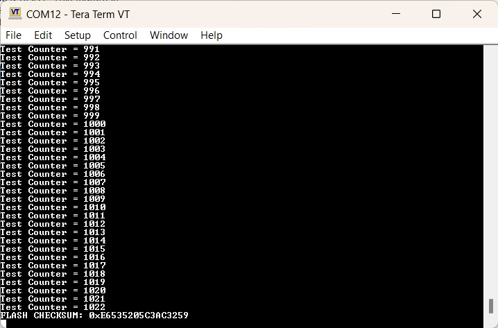
- To speed up the process of testing the flash checksum outputs, use a
UART. This feature is implemented in Class B firmware. It will print
the calculated checksum value when the stored flash checksum does
not match the calculated flash checksum. To use this project, set
the UART parameters shown in Figure 12.
- Read the checksum in debug mode
- Copy this checksum value and store it in the checksum location, but ensure
that the PSOC™ 6 MCU uses little endian format.
The project for the GCC compiler is shown in Figure 13.
Figure 13. Reassign checksum constant with actual checksum 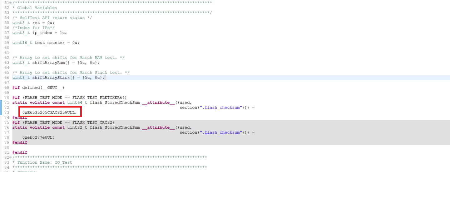
- Compile the project and program PSOC™ device
Appendix B: IEC 60730-1 certificate of compliance
Appendix C: Supported part numbers
The certified libraries support the following PSOC™ 6 MCU families:
| Device family | Datasheet |
|---|---|
| PSOC™ 61x4 | PSOC™ 61 MCU: CY8C61x4 datasheet |
| PSOC™ 62x4 | PSOC™ 62 MCU: CY8C62x4 datasheet |
| PSOC™ 61x5 | PSOC™ 61 MCU: CY8C61x5 datasheet |
| PSOC™ 62x5 | PSOC™ 62 MCU: CY8C62x5 datasheet |
| PSOC™ 61x6/61x7 | PSOC™ 61 MCU Arm® Cortex®-M4 |
| PSOC™ 62x6/62x7 | PSOC™ 62 MCU Arm® Cortex®-M4 |
| PSOC™ 61x8/61xA | PSOC™ 61 MCU: CY8C61x8, CY8C61xA datasheet |
| PSOC™ 62x8/62xA | PSOC™ 62 MCU: CY8C62x8, CY8C62xA datasheet |
For details on the supported part numbers, see the ordering information section of the corresponding device datasheet.
Appendix D: MISRA compliance
| Component | Name | Version |
|---|---|---|
| Test specification | MISRAC:2012 guidelines for the use of the C language in critical systems | 3rd edition, Feb 2019 |
| Target device | CY8C61x, CY8C62x, CY8C63x, CY8C64x | Production |
| Target compiler | GCC | v11.3.1 |
| Generation tool | ModusToolbox™ | v3.3 |
| Peripheral Driver Library | PDL | mtb-pdl-cat1 V3.14.0 |
| MISRA checking tool | Coverity Static Analysis Tool | 2022.12.0 |
| MISRA-C:2012 rule | Rule class (R/A) | Rule description | Description of deviation(s) |
|---|---|---|---|
| 1.1 | R | Any implementation defined behavior on which the output of the program depends shall be documented and understood | Violated because PDL supports GCC, IAR, and MDK-Arm® compilers. Refer to the compiler documentation for the compiler-specific behavior |
| 4.1 | R | Run-time failures shall be minimized | Some drivers can contain redundant operations introduced because of generalized implementation approach |
| 4.3 | R | The character sequences /* and // shall not be used within a comment | SRAM STL driver contain c syntax within assembly code |
| 4.4 | R | Sections of code should not be "commented out" | Some comments resemble code snippet for better understanding |
| 4.5 | R | Identifiers in the same name space with overlapping visibility should be typographically unambiguous | PDL uses auto-generated header files and expected to have common prefixes for macros |
| 4.6 | A | Typedefs that indicate size and signedness should be used in place of the basic numerical types | This rule is currently disabled in the analysis configuration |
| 4.8 | A | If a pointer to a structure or union is never dereferenced within a translation unit, then the implementation of the object should be hidden | This rule is currently disabled in the analysis configuration |
| 4.9 | A | A function should be used in preference to a function-like macro where yet are interchangeable | Deviated since function-like macros are used to allow more efficient code |
| 1.1 | R | The program shall contain no violations of the standard C syntax and constraints, and shall not exceed the implementation ’ s translation limits | The middleware library supports ISO:C99 standard |
| 1.2 | R | Language extensions should not be used | The middleware library supports ISO:C99 standard |
| 1.3 | R | There shall be no occurrence of undefined or critical unspecified behavior | This specific behavior is explicitly covered in rules 5.1, 21.1 |
| 2.3 | R | A project should not contain unused type declarations | STL is a library that provides API to the hardware. The type is part of API, which is defined for application-level only |
| 2.4 | R | A project should not contain unused tag declarations | STL is a library that provides API to the hardware. The tag like enums is part of API, which are defined for application-level only |
| 2.5 | R | A project should not contain unused macro definitions | STL is a library that provides API to the hardware. The macro is part of API, which is defined for application-level only |
| 3.1 | R | The character sequences \/* and \/\/ shall not be used within a comment | Allow doxygen-style comments |
| 5.1 | R | External identifiers shall be distinct | This rule applies to ISO:C90 standard. STL conforms to ISO:C99 that does not require this limitation |
| 5.2 | R | Identifiers declared in the same scope and name space shall be distinct | This rule applies to ISO:C90 standard. STL conforms to ISO:C99 that does not require this limitation |
| 5.3 | R | An identifier declared in an inner scope shall not hide an identifier declared in an outer scope | This rule applies to ISO:C90 standard. STL conforms to ISO:C99 that does not require this limitation |
| 5.4 | R | Macro identifiers shall be distinct | This rule applies to ISO:C90 standard. STL conforms to ISO:C99 that does not require this limitation |
| 5.5 | R | Identifiers shall be distinct from macro names | This rule applies to ISO:C90 standard. STL conforms to ISO:C99 that does not require this limitation |
| 5.8 | R | Identifiers that define objects or functions with external linkage shall be unique |
During the code analysis, the same source files are compiled multiple times with device-specific options. All object and function identifiers are actually unique for each specific run |
| 5.9 | A | Identifiers that define objects or functions with internal linkage should be unique |
This rule is currently disabled in the analysis configuration |
| 8.3 | R | All declarations of an object or function shall use the same names and type qualifiers |
This rule is currently disabled in the analysis configuration. |
| 8.4 | R | A compatible declaration shall be visible when an object or function with external linkage is defined |
This rule is currently disabled in the analysis configuration |
| 8.5 | R | An external object or function shall be declared once in one and only one file |
This rule is currently disabled in the analysis configuration. |
| 8.6 | R | An identifier with external linkage shall have exactly one external definition. |
This rule is currently disabled in the analysis configuration |
| 8.7 | A | Functions and objects should not be defined with external linkage if they are referenced in only one translation unit | The middleware library provides API to the hardware. The functions and objects with external linkage are part of API, which are defined for application-level only |
| 8.13 | A | A pointer should point to a const-qualified type whenever possible | This rule is currently disabled in the analysis configuration |
| 11.1 | R | Conversions shall not be performed between a pointer to a function and any other type | The cast from unsigned int to pointer does not have any unintended effect, as it is a consequence of the definition of a structure based on hardware registers |
| 11.2 | R | Conversions shall not be performed between a pointer to an incomplete type and any other type | The cast from unsigned int to pointer does not have any unintended effect, as it is a consequence of the definition of a structure based on hardware registers |
| 11.4 | A | A conversion should not be performed between a pointer to object and an integer type | The cast from unsigned int to pointer does not have any unintended effect, as it is a consequence of the definition of a structure based on hardware registers |
| 11.6 | R | A cast shall not be performed between pointer to void and an arithmetic type | The cast from unsigned int to pointer does not have any unintended effect, as it is a consequence of the definition of a structure based on hardware registers |
| 11.8 | R | A cast shall not remove any const or volatile qualification from the type pointed to by a pointer | Drivers access hardware register by macro, which is used for both read and write access. In that case remove of const qualification does not have any unintended effect, as it is a consequence of the macro usage |
| 13.2 | R | The value of an expression and its persistent side effects shall be the same under all permitted evaluation orders |
This rule is currently disabled in the analysis configuration |
| 14.3 | R | Controlling expressions shall not be invariant |
This rule is currently disabled in the analysis configuration |
| 15.5 | A | A function should have a single point of exit at the end |
This rule is currently disabled in the analysis configuration |
| 18.4 | A | The +, -, += and -= operators should not be applied to an expression of pointer type | There are several instances of pointer arithmetic in drivers. They cannot be avoided, so are manually checked and reviewed to be safe |
| 20.4 | R | A macro shall not be defined with the same name as a keyword | There are some CMSIS-CORE defines are used for structure members definitions that cannot be enclosed in parentheses |
| 21.1 | R | #define and #undef shall not be used on a reserved identifier or reserved macro name | STL header files contain preprocessor guard macros with leading underscores. STL uses CMSIS macros with leading underscores and therefore inherits its MISRA violations |
| 21.2 | R | A reserved identifier or macro name shall not be declared | STL header files contain preprocessor guard macros with leading underscores. STL uses CMSIS macros with leading underscores and therefore inherits its MISRA violations |
References
- IEC 60730 Standard: Automatic electrical controls for household and similar use, IEC 60730-1 Edition 3.2, 2007-03; Available online
- IEC 61508 Standard: Functional safety of electrical/electronic/programmable electronic safety-related systems, IEC 61508-2 Edition 2.0, 2010-04; Available online
ADC
analog-to-digital converter
ADC
ADDR
address
ADDR
AMUX
analog multiplexer
AMUX
CAN FD
controller area network with flexible data-rate
CAN FD
CRC
cyclic redundancy check
CRC
DAC
digital-to-analog converter
DAC
DMA
direct memory access
DMA
DW
DataWire
DW
EEPROM
electrically erasable programmable read-only memory
EEPROM
EMC
electromagnetic compatibility
EMC
FIFO
first in, first out
FIFO
FPU
floating point unit
FPU
GPIO
general-purpose I/O
GPIO
HSIOM
high-speed I/O matrix
HSIOM
ID
identification
ID
ILO
internal low-speed oscillator
ILO
IMO
internal main oscillator
IMO
IPC
inter-processor communication
IPC
ISR
interrupt service routine
ISR
LCD
liquid crystal display
LCD
LSB
least significant byte
LSB
LUT
lookup table
LUT
MBIST
Memory Built-In Self Test
MBIST
MISRA
motor industry software reliability association
MISRA
MSB
most significant byte
MSB
NDA
non disclosure agreement
NDA
PC
program counter
PC
PDL
peripheral driver library
PDL
SAR
successive approximation register
SAR
SCB
Serial Communication Block
SCB
SFlash
Supervisory flash
SFlash
SIL
safety integrity level
SIL
SP
stack pointer
SP
SPI
Serial Peripheral Interface
SPI
TCPWM
timer/counter pulse-width modulation (or modulator)
TCPWM
WDT
watchdog timer
WDT
Revision history
| Document revision | Date | Description of changes |
|---|---|---|
| ** | 2024-09-30 | Initial release |
| *A | 2025-03-17 | Updated document to include the latest ModusToolbox™ Safety Test Library version |
Trademarks
PSOC™, formerly known as PSoC™, is a trademark of Infineon Technologies. Any references to PSoC™ in this document or others shall be deemed to refer to PSOC™.