AN239061 Getting started with PSoC™ 64 security
About this document
Scope and purpose
This document demonstrates how to build and execute a simple blinky application on a PSoC™ 64 secured MCU. Additionally, it provides a basic understanding on provisioning the process, secure boot validations, key generation, and image signing.
Intended audience
This document is intended for developers who are using the PSoC™ 64 secured MCU.
Introduction
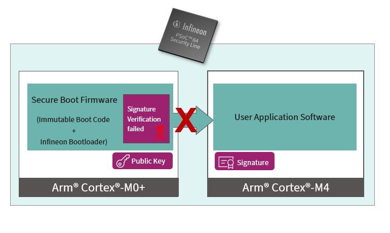
The PSoC™ 64 secured MCU line, based on the PSoC™ 6 MCU platform, features out-of-box security functionality. At a high level, PSoC™ 64 consists of two cores: Cortex®-M0+ and Cortex®-M4. The bootloader runs on the Cortex®-M0+ core and is considered as a secure core and the user application runs on the Cortex®-M4 core. The authenticity of the user application on Cortex®-M4 is always validated by the Cortex®-M0+ bootloader before handing over the control to the user application on this secured MCU. In a secure boot functionality, Infineon provides an immutable boot code programmed in a factory that launches an Infineon bootloader. The bootloader is itself signed, so that the boot code can verify the integrity of the bootloader. This bootloader then verifies the signature of user application software that should run on the device before launching it. The device fails to boot in case of failed authentication, as shown in Figure 1. For more details, see the “Secure Boot” SDK user guide.
Figure 1. Secure boot validation (failure)
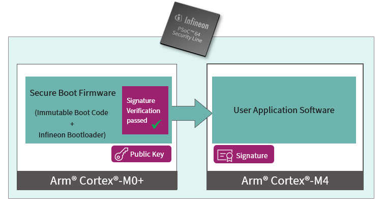
On successfully validation the signature of the user application software, the Infineon bootloader passes the control to the user application on the Cortex®-M4 core.
Figure 2. Secure boot validation (success)
To develop with a PSoC™ 64 secured MCU, firstly, you must provision the device with keys and policies, and then program the device with signed firmware. The policies are a set of rules to be enforced on the device such as defining the flash partitions, setting protection rules for debug ports, and so on. The keys are used to validate the signed firmware on the device as a part of the secure boot process. The device fails to boot if the firmware validation fails.
Terms definition
- ModusToolbox™: The ModusToolbox™ software is a modern, extensible development environment supporting a wide range of Infineon microcontroller devices
- Root of trust (RoT): This is an immutable process or identity used as the first entity in a trust chain. No ancestor entity can provide a trustable attestation (in digest or other form) for the initial code and data state of the RoT
JSON: It is a lightweight format for storing and transporting data
JWT: JSON Web Token is an open industry standard that defines a compact and self-contained way for securely transmitting information
Policy: A set of rules that are enforced on a device
Keys: Key is a P-256 ECC key-pair used by the encryption and decryption algorithms to encrypt and decrypt data
- Provisioning: It is the process of injecting secure assets (for example, keys, policies, and certificates) into the device
Getting started
This section demonstrates a quick hands-on exercise on how to create a basic security project, program, and execute it. This helps you to get started with the secured application without going deep into the security concepts of the PSoC™ 64 device.
Prerequisites
To provision the assets and keys, and setting up the development environment on the device for the blinky code example, install the following:
ModusToolbox™ software
, v3.0 or later. For more details, see the
ModusToolbox™ installation guide
Note:Python is no longer bundled with ModusToolbox™ 3.2 or later on Windows. In most cases, install Python version 3.8.10 to 3.11. See Using Python with a ModusToolbox™ application to set it up in Python with ModusToolbox™ 3.2. This content has been tested with ModusToolbox™ 3.2 with Python 3.8.10
- “Secure Boot” SDK package ("CySecureTools" v6.0.0 or later). For more details, see the cysecuretools on GitHub page
- ModusToolbox™ Edge Protect Security Suite package, v1.0.0 or later. For installation and more details, see the ModusToolbox™ Setup program user guide
Create ModusToolbox secure application (Secure Blinky
App)
After installing the ModusToolbox™ software, do the following to create a new project under a new workspace or existing workspace.
- Launch the Eclipse IDE for ModusToolbox™
- Click
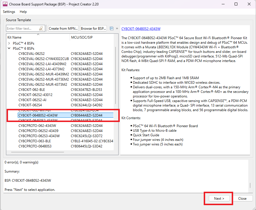
Select the suitable kit in the Project Creator (for example, CY8CKIT-064B0S2-4343W) and click
Next >
Figure 3. Create a new ModusToolbox™ Application

Figure 4. Selecting the kit
Select the Secure Blinky LED FreeRTOS application under Getting Started and click Create. This may take a while as it pulls all required sources from respective repositories
Figure 5. Selecting the application
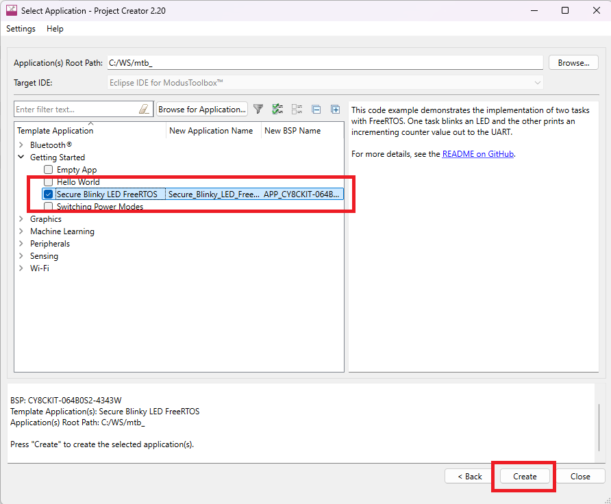
The earlier step creates a blinky application that executes on CM4 core and CM0+ core hosts the bootloader.
Connecting the kit
Connect the kit to the PC using the provided USB cable through the KitProg3 USB connector. Ensure that you remove the jumper shunt from J26 to change the VCC_3V3 voltage to 2.5 V and the jumper shunt on J14 is placed in the VCC_3V3 position (between pin 2 and 3) before plugging in the kit to the PC. The 2.5 V supply is necessary for provisioning, where PSoC™ 64 eFuses are blown. KitProg3 must be in the DAPLink mode for provisioning. The Status LED (LED2) will be ramping ON/OFF (~2 Hz) in this mode. Press and release the Mode button (SW3) one or more times until the KitProg3 is in the DAPLink mode.
| PSoC™ 64 VTARG | J14 position | J26 |
|---|---|---|
| 1.8 V | VCC_1V8 | X |
| 2.5 V | VCC_3V3 | Not loaded |
| 3.3 V | VCC_3V3 | Loaded |
"CySecureTools" setup
"CySecureTools" is a command-line tool that contains all the necessary scripts for generating the policies, creating key pairs, provisioning the device, signing the user application, and creating the certificate. After installing the "CySecureTools", generate the policies and keys to be provisioned into the device using any of the following:
- Command-line interface
- Secure Policy Configurator (GUI)
Command-line interface
- Open the modus-shell program provided as part of ModusToolbox™ installation, which can be accessed from the Windows search box
- Navigate to the %WORKSPACE%/Secure_Blinky_LED_FreeRTOS/ directory in the workspace
Run the following command in modus-shell:
Note: This example uses the CY8CKIT-064B0S2-4343W kit. You can use any of the PSoC™ 64 kits.
cysecuretools -t <target_parameter> init
The <target_parameter> for "CySecureTools" can either be the kit name or the device family name, as shown in Table 2. In this document, the device family name is used in the example. A user with a custom board will most likely use the device family name too. The following two commands are the same:
cysecuretools -t cyb06xxa init
(or)
cysecuretools -t cy8ckit-054b0s2-4343w init
This command provides default policies generated in the /policy folder and other secure assets that can be used to set up the chip with development parameters, such as leaving the Cortex®-M4 Debug Access Port (DAP) open to reprogram the chip.
Based on the selected target, this step sets up all the necessary files in the workspace that are used for subsequent steps and generates multiple policy files in the %WORKSPACE%/Secure_Blinky_LED_FreeRTOS/policy folder.
| Kit | "CySecureTools" target parameter | Description | |
|---|---|---|---|
| Kit name | Device family name | ||
| CY8CKIT-064B0S2-4343W | cy8ckit-064b0s2-4343w | cyb06xxa | Device with 2 MB flash |
| CY8CPROTO-064B0S3 | cy8cproto-064b0s3 | cyb06xx5 | Device with 512 KB flash |
Device policy
As mentioned earlier, a policy is a JSON file that defines the device's operating modes, debug access, code updates, and so on. The policy is injected into the device during the provisioning. The CySecureTools init command generates multiple default device policies in the /policy folder and you can pick any policy to proceed further to create the keys and provision the device. In this example, policy_single_CM0_CM4_swap.json is chosen as the device policy.
This policy is for applications that need to have a single signature for two combined applications, that is, secure Cortex®-M0+ and user app on Cortex®-M4.
Table 3 shows a high-level overview of a policy. For a detailed description of policy parameters, see the "Secure Boot" SDK user guide.
| Feature | Policy setup |
|---|---|
| “Secured” coprocessor debug port | Open |
| CM4 debug port | Open |
| SysAP debug port | Open |
| CM4 (application) flash size | 1152 KB |
| External memory enabled for update? | Yes |
| Re-provisioning enabled? | Yes |
Creating new public and private key pair for signing
After creating the policy, generate the keys to provision the device. An asymmetric key pair consists of a public and private key. It is used to generate and verify the signature over a chunk of data (bootloaders, user images, and so on). In an asymmetric cryptography, the sender shares the public key with everyone in the system and keeps the private key with the self. Whenever the sender wants to send any data securely, they sign the data with the private key and the receiver verify the data with a public key. The message encrypted with the private key cannot be decrypted without the corresponding public key. Therefore, ensuring the security of the data exchanged.
To generate a key pair, ensure that you are in the %WORKSPACE%/Secure_Blinky_LED_FreeRTOS/ directory and run the following command in the modus-shell:
cysecuretools -t cyb06xxa -p policy/policy_single_CM0_CM4_swap.json create-keys
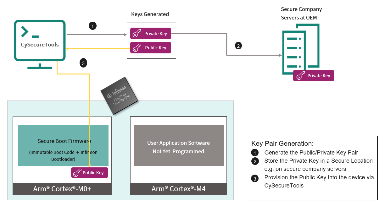
“CySecureTools” reads the provided policy and generates the keys as defined in the policy file. The keys are generated in the /Keys/ folder. By default, only one key, the USERAPP_CM4_KEY, a P-256 elliptic curve key pair, is generated with this command. The tool generates keys in two formats: PEM and JSON. Both the PEM and JSON files represent the same key. This key is used to sign the application software image.
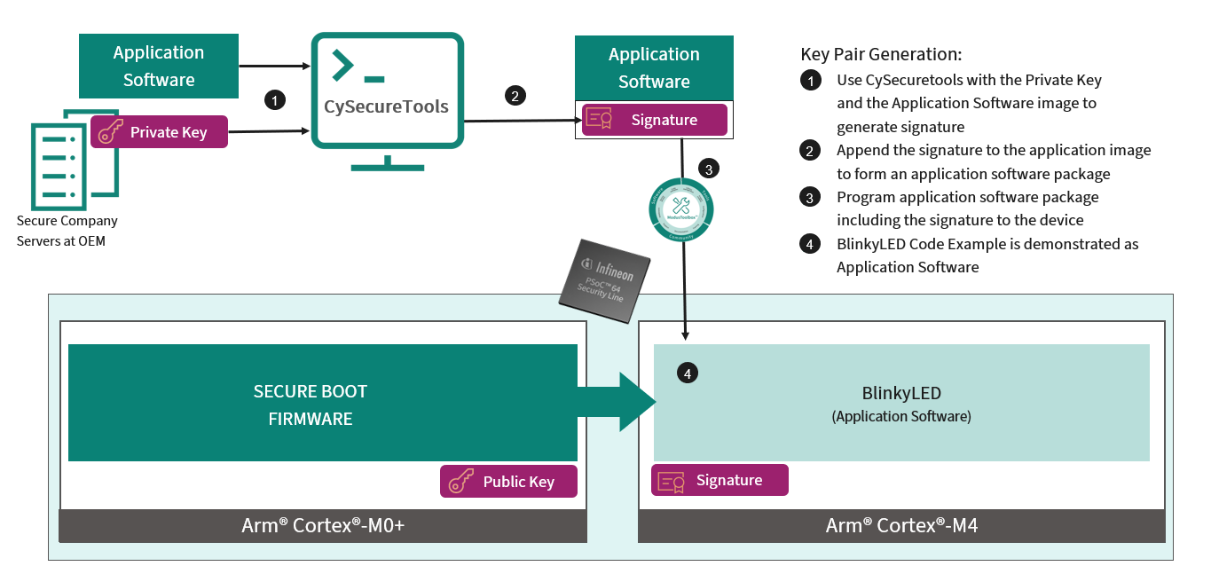
Figure 6 shows the key generation and provisioning flow.
Figure 6. Flow diagram of key pair generation
Provisioning the device
Provisioning is a process of injecting the keys, certificates, and bootloader image to the device. Do the following to provision the device:
- Connect the PSoC™ 64 kit to the host machine where the "CySecureTools" is installed via the provided USB cable through the KitProg3 USB connector (J6)
Once connected, put the device in DAPLink mode by pressing the mode select SW3 switch provided on the kit.
In this mode, the Status LED (LED2) will be ramping ON/OFF fast (~2 Hz). The kit supply voltage must be 2.5 V in this step. For voltage configurations, see the Connecting the kit
Ensure that you are in the %WORKSPACE%/Secure_Blinky_LED_FreeRTOS/ directory. In the command-line, run the following command for provisioning the assets to the device:
cysecuretools -t <target_parameter> -p policy/policy_single_CM0_CM4_swap.json provision-DeviceE.g.: cysecuretools -t cyb06xxa -p policy/policy_single_CM0_CM4_swap.json provision-deviceNote: Ensure that you pass the correct target parameter in the command. For more details, see Table 1- To see the progress of the device provisioning, open the device serial COM port over Tera Term or Putty in the host machine with a 115200 baud rate. On successful provisioning of the assets, see the "PROVISIONING PASSED" message on the serial terminal
As mentioned earlier, the policies, keys generation, and provisioning can also be done via a GUI tool called “Secure Policy Configurator” to be discussed in the following section. For more details on provisioning, see PSoC™ 64 provisioning specification.
Secure Policy Configurator
The “Secure Policy Configurator”, which is available with the ModusToolbox™ Edge Protect Security Suite package as mentioned in Prerequisites. For more details, see the Secure Policy Configurator user guide. Use the "Secure Policy Configurator" to create a new or edit existing policy configuration files for the PSoC™ 64 "Secure Boot" MCU devices and provision devices. The "Secure Policy Configurator" provides easy execution of the configuration without using the command line. Additionally, it provides editing a policy file via a GUI without editing the XML policy file. This configurator internally uses "CySecureTools" for generating policies, keys, and provisioning.
In the Command-line interface section, the command line is used to send the provisioning command to provision the device. This section explains how to provision a device via the "Secure Policy Configurator". To open the Configurator, go to the ModusToolbox™ Project Explorer and right click on the project and traverse as shown in Figure 7. Alternatively, you can also launch it from the Quick Panel, scroll down, and click on the "Secure Policy Configurator" tool in Library Configurators.
Figure 7. Secure Policy Configurator
!(img/dig1725255423569.svg)
Once the "Secure Policy Configurator" tool is launched, go to File > New, probe the appropriate kit (CY8CKIT-064B0S2-4343W in this case), Project directory and Target, as shown in Figure 8 and click OK. This step creates the default policies and keys in /policy and /keys folder inside %WORKSPACE%/Secure_Blinky_LED_FreeRTOS.
Figure 8. Select Target
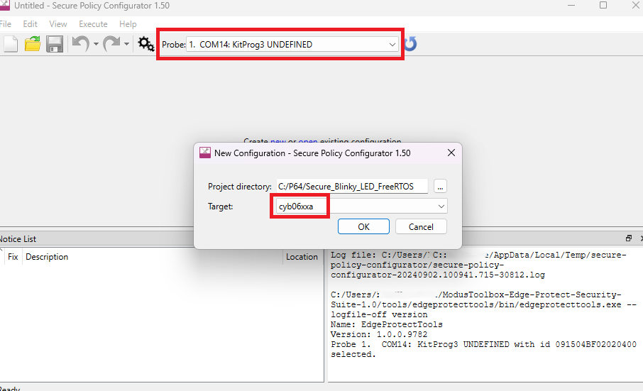
By default, the tool does not generate the user keys. Therefore, generate the user application keys explicitly in the /keys folder via the command line before provisioning the device. See Creating new public and private key pair for signing for generating USERAPP_CM4_KEY.
After generating the policies and keys, it opens the generated policy, as shown in Figure 9. By default, the generated policy is policy_single_CM0_CM4_swap.json.
Figure 9. Policy
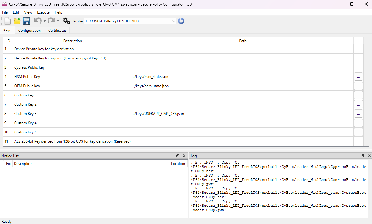
You can see the policy fields displayed in the Policy Configurator. You can either provision the device as mentioned in the Provisioning the device section or edit and provision the policy as explained in the following sections.
Editing a policy
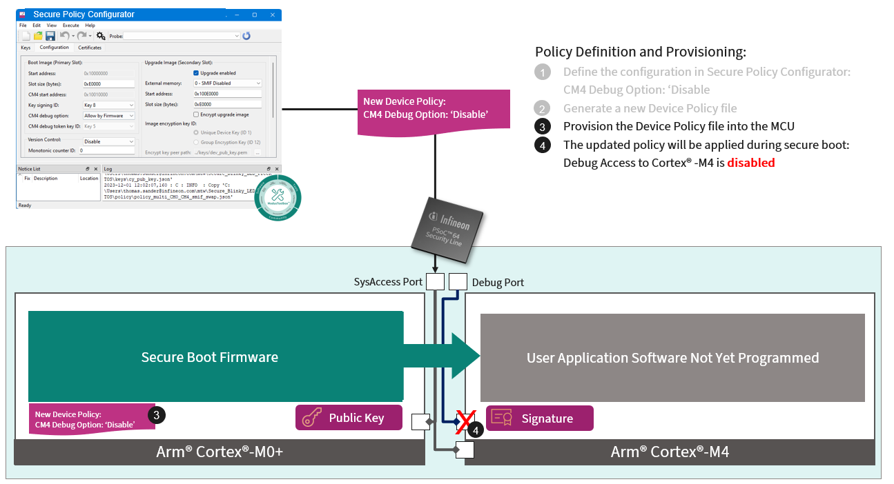
Edit the policies as per your requirement. An example is demonstrated to edit the policy and provision the device. Under the Configuration tab, disable the Cortex®-M4 debug port by selecting the Disable option, and save the changes, as shown in Figure 10. This generates a new policy file overwriting the old file in the/policy folder and provisioned to the device.
Figure 10. Secure Policy Configurator
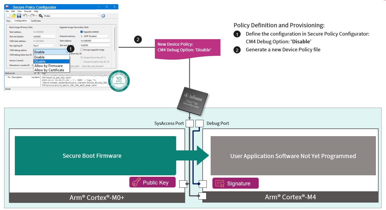
Once the policy is provisioned to the device, the debug policy is enforced on the device and the debug port of Cortex®-M4 is disabled, as shown in Figure 11.
Figure 11. Secure Policy Configurator
For more information on this tool and options, go to Help > View Help in the tool window.
Provisioning the device
Provision the device as shown in Figure 12.
Figure 12. Provisioning the device
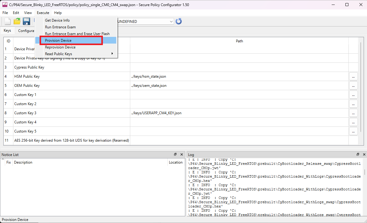
The status of provisioning can be seen in the log window.
Build and run the secure application
Ensure that the device is provisioned before executing the secured application on the device. Put the MiniProg4 or KitProg back into CMSIS-DAP Bulk mode before attempting to program or debug the device. Now, reconnect the kit to power then press and release the Mode button (SW3) one or more times until the KitProg3 is in the CMSIS-DAP Bulk mode. The Status LED (LED2) will be solid in this mode.
Additionally, if the voltage is set to 2.5 V for provisioning, it should be changed back to the normal operating voltage before programming the application. Do the following to build and run the secured application:
- In the Project Explorer, right-click on the Secure_Blinky_LED_FreeRTOS project and select Build Project
- Ensure that the device is connected to the host machine over USB
- Right-click on Secure_Blinky_LED_FreeRTOS project and select
- On the dialog, select and click the Run button
Once the build is complete, you will see in the ModusToolbox™ console that “CySecureTools” has signed the image with the keys you generated in the Creating new public and private key pair for signing section. The following messages are shown in the build console window before the memory consumption table, as shown in Figure 13:
- “Image for slot BOOT signed succesfully”
- “Image for slot UPGRADE signed succesfully”
Figure 13. ModusToolbox™ console after build is complete

As part of the build process mentioned above, the signature of the application software image is generated by the "CySecureTools" (part of the post build scripts) using the Private key generated from Creating new public and private key pair for signing and appends to the end of the application software image.
Figure 14. Application software image signature generation
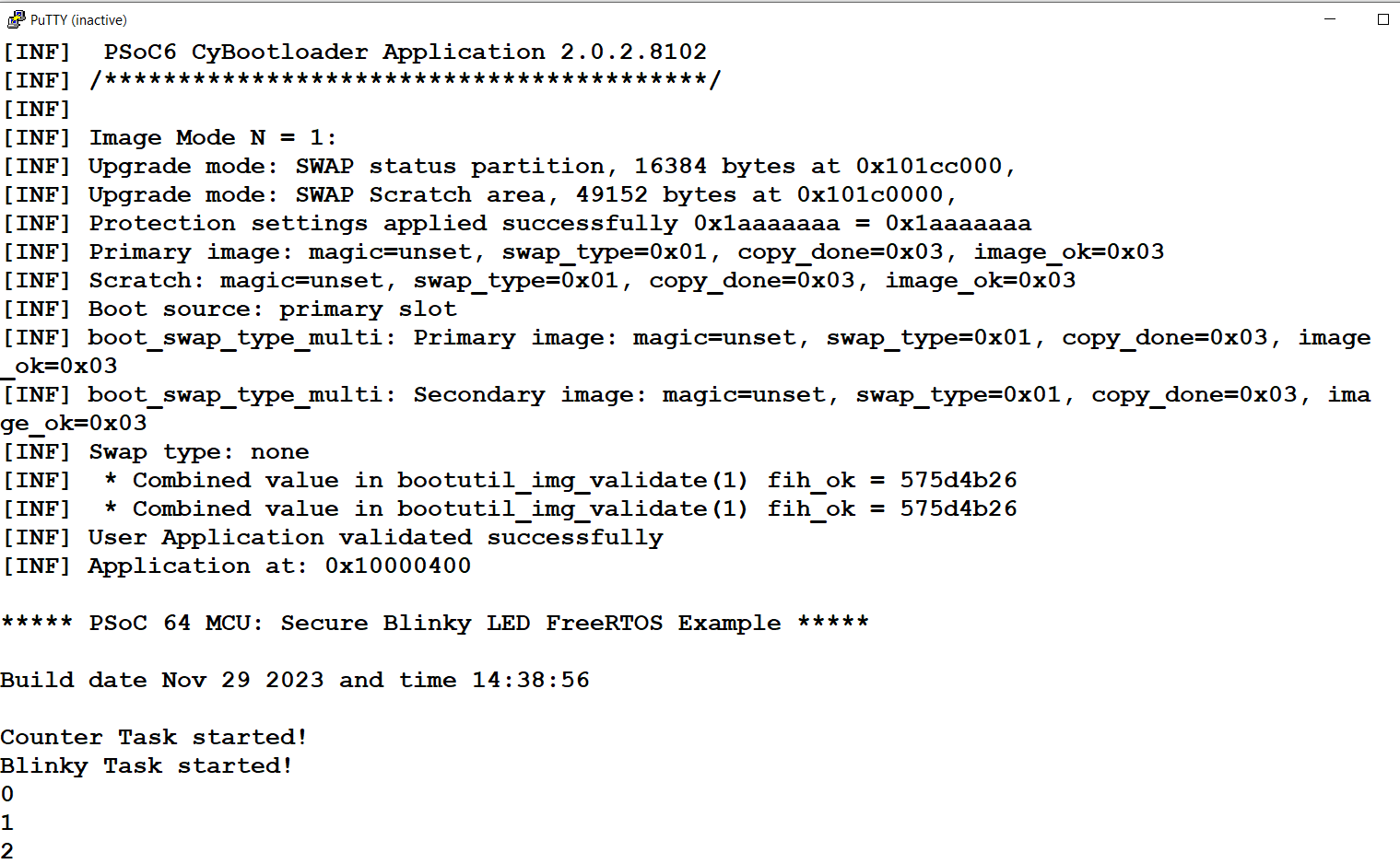
Immediately after the build, it flashes the images to the device and boots the application. Observe LED8 (Orange) blinking every second. Open a serial terminal with a baud rate of 115200 to see the application logs, as shown Figure 15. This confirms that the application is loaded successfully and running
Figure 15. Application logs
Debugging the application
- Right-click on Secure_Blinky_LED_FreeRTOS project and select
- On the dialog, select and click Debug button
A breakpoint is set at the main function with default launch configurations. After step 3, the debugger breaks at the main function of the blinky application. Now you can start debugging the code starting from the main function.
References
This section contains various links to the resources that can be useful when working with the application note.
| Document | Name/description |
|---|---|
| Application notes | |
| AN227860 | "Secure Boot" SDK user guide |
| AN228571 | Getting started with PSoC™ 6 MCU on ModusToolbox™ software |
PSoC™ 64 provisioning specification | PSoC™ 64 Provisioning specification guide |
| Code examples | |
| CE228684 | PSoC™ 64 MCU: Secure blinky LED with FreeRTOS |
| PSoC™ 6 code examples | PSoC™ 6 MCU code example list |
| Device documentation | |
| PSoC™ 6 MCU datasheets | PSoC™ 64 MCU datasheets |
| PSoC™ 6 reference manuals | PSoC™ 64 MCU reference manual |
| Libraries (on GitHub) | |
| mtb-pdl-cat1 | PSoC™ 6 Peripheral Driver Library (PDL) |
| mtb-hal-cat1 | Hardware Abstraction Layer (HAL) library |
| retarget-io | A utility library to retarget the standard I/O (STDIO) messages to a UART port |
| p64-utils | PSoC™ 64 “Secure Boot” utilities middleware library |
| PSoC™ 6 middleware | PSoC™ 6 middleware libraries |
| Tools | |
| ModusToolbox™ | ModusToolbox™ software installation |
| CySecureTools | "CySecureTools" installation |
Revision history
Document revision | Date | Description of changes |
|---|---|---|
** | 2023-12-15 | Initial release |
| *A | 2024-09-11 | Updated the Python version and Secure Policy Configurator section |