AN237138 Getting started with Matter over Wi-Fi on PSoC™ 6 MCUs in ModusToolbox
About this document
Scope and purpose
AN237138 describes how to create and use the Matter Lock device using PSoC™ 6 with CYW43xxx. The topics covered include the Matter protocol introduction, PSoC™ 6 introduction, and tools & methods supported to achieve the necessary result.
Intended audience
This application note is intended for users who want to start Matter device development. Users must have basic knowledge about Matter protocol and terminologies defined under it. The device type mentioned in this document is 'Door Lock' and the component used is Infineon's PSoC™ 6 & CYW43xxx.
Introduction to Matter Protocol
Overview of Matter
Matter is an open standard for smart home technology and IoT, which lets your device work with any Matter-certified ecosystem using a single protocol. Matter is introduced by Connectivity Standards Alliance, an organization of hundreds of companies creating products for smart home and IOT.
Matter's goal is to be an interoperable standard that fosters technology adoption and innovation, gradually replacing proprietary protocols for smart home ecosystems.
Matter is implemented by an open source SDK that contains not only the implementation of the specification but also a rich set of examples and interoperable code. The core Matter protocol fits on the top three layers in the context of OSIwhich means it can run over any type of IPv6 transport and network. While control and other operational communication is performed over IPv6, Bluetooth® Low Energy and NFC may be employed to commission new devices.
Figure 1 illustrates the Matter Protocol layer alongside TCP/IP and OSI layers.
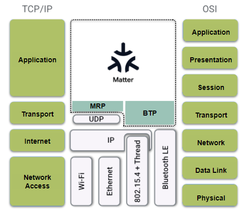
Matter is flexible and interoperable. It builds upon years of challenges and successes of low-power 802.15.4 networks as well as Wi-Fi smart home devices. Like Thread, Matter builds atop IPv6. It includes strong cryptography, a well-defined modelling of device types and their data, and the support for multiple ecosystem administrators.
Matter also supports bridging of other Smart Home technologies such as Zigbee, Bluetooth Mesh and Z-Wave. This means that devices based on these protocols may be operated as if they were Matter devices through a Bridge, which is a member device of both a Matter network and the other, bridged, IoT technologies.
There is a dual advantage to Bridges. The devices that use other protocols gain access to technologies and ecosystems that target native Matter devices. Meanwhile Matter will leverage on mature technologies with large installed user bases to create a true web of connected things.
Reasons to build with Matter include:
- Lower latency and higher reliability than cloud-to-cloud connection, because Matter is an IP-based local connectivity protocol.
- Lower development costs: build once and it works for all Matter-certified ecosystems.
- Consistent setup experience across all Matter-enabled devices.
- Device sharing and control via other Matter-compatible ecosystems.
- Wide variety of supported devices with different hardware platforms (Wi-Fi-Thread-Ethernet) being interoperable.
Matter terminology
- Node: An addressable entity which supports the Matter protocol stack and (once commissioned) has its own Operational Node ID and Node Operational credentials. A device may host multiple nodes.
- Fabric: A logical collection of communicating nodes, sharing a common root of trust, and a common distributed configuration state.
- Commissioning: Sequence of operations to bring a node into a fabric by assigning an Operational Node ID and Node Operational credentials.
- Commissionable Node: A node that is able to be commissioned. Specific actions such as a button press may be required to put a Commissionable Node into Commissioning Mode for it to allow Commissioning.
- Commissionable Node Discovery: Discovery of a node that is able to be commissioned, but not necessarily in Commissioning Mode, for the purpose of performing commissioning. The node may be brand new, after factory reset, or it may have already been commissioned.
- Commissioner: A role of a node that performs commissioning.
- Commissionee: An entity that is being commissioned to become a node.
- Commissioning Channel: A Secure Channel used to perform commissioning (BLE, NFC etc.).
- Cluster: A specification defining one or more attributes, commands, behaviors, and dependencies, that supports an independent utility or application function. The term may also be used for an implementation or instance of such a specification on an endpoint.
Matter Door Lock application
Using a device type in the Matter ecosystem is important due to simplicity and clear guidance for a particular set of predefined devices. Door Lock is a device type defined in Matter implementation which shall contain all mandatory clusters and attributes listed under it. The function of a Door Lock device is to actuate a door lock by means of a manual or remote method.
To achieve this, CSA has defined following clusters under "Door Lock" device.
| ID | Cluster name | Client/Server | Conformance |
|---|---|---|---|
0x0003 | Identify | Server | Mandatory |
0x0004 | Groups | Server | Optional |
0x0005 | Scenes | Server | Optional |
0x0101 | Door Lock | Server | Mandatory |
0x0009 | Alarms | Server | Optional |
0x0020 | Poll Control | Server | Optional |
0x000A | Time | Client | Optional |
0x0038 | TimeSync | Client | - |
Among these clusters, the Identify and Door Lock clusters are mandatory and the rest are user-implementation dependent. There are several attributes which support different action values. Please refer to the latest Matter Device library for further details. There are two commands supported under the Door Lock cluster which shall trigger door locking or unlocking where the user has to implement the actual action for door lock (driving actuator/motor).
| ID | Name | Direction | Response | Access | Conformance |
|---|---|---|---|---|---|
0x00 | Lock Door | Client ⇒ Server | Y | T O | Mandatory |
0x01 | Unlock Door | Client ⇒ Server | Y | T O | Mandatory |
Underlying dependent parameters like pin code and RFID code, if set, shall also be taken into consideration while operating with these commands.
Attributes serve the purpose of defining or setting/changing values of parameters such as Pin code, Day/Date, Timeout etc. These are available under each cluster and can be accessed when required. The following table provides a sample.
| ID | Name | Type | Constraint | Quality | Default | Access | Conformance |
|---|---|---|---|---|---|---|---|
0x0000 | LockState | enum8 | desc | X P S | R V | Mandatory | |
0x0001 | LockType | enum8 | desc | R V | M | ||
0x0002 | ActuatorEnabled | bool | all | R V | M | ||
0x0003 | DoorState | enum8 | desc | X P | R V |
For more details on Clusters, Attributes, Endpoints, and related terminologies, please refer to the Matter specifications listed here.
Development ecosystem
PSoC™ 6 resources
A wealth of data is available at http://www.infineon.com/ to help you to select the right PSoC™ device and quickly and effectively integrate it into your design. The following is an abbreviated list of resources for PSoC™ 6 MCU:
- Overview:PSoC™ Portfolio
- Product Selectors:PSoC™ 6 MCU
- ModusToolbox™ Software for developing PSoC™ 6 MCU applications: ModusToolbox™ Software is a modern, extensible development environment supporting a wide range of Infineon microcontroller devices including PSoC™ 6 MCU.
PSoC™ 6 Datasheets describe and provide electrical specifications for each device family.
PSoC™ 6 Development Kits: Infineon provides a wide selection of hardware development kits for getting stated on PSoC™ 6, and to rapidly prototype applications.
PSoC™ 6 Application Notes cover a broad range of topics, from basic to advanced level spanning hardware, firmware, software, and application level topics. Many of the application notes include associated code examples.
- Code examples: There are hundreds of code examples available in ModusToolbox™ software that enables you to easily get started on PSoC™ 6, and rapidly prototype your application. Each code example provides a README.md file to learn more about that code example, as well as how to use it to create an application.
- Technical Reference Manuals (TRMs) provide detailed descriptions of the architecture and registers in each device family.
PSoC™ 6 Programming Specification provide the information necessary to program the nonvolatile memory of the PSoC™ 6 MCU devices.
- CAPSENSE™ Design Guides: Learn how to design capacitive touch-sensing applications with PSoC™ devices.
- Training videos: Infineon provides video training on our products and tools, including a dedicated series on PSoC™ 6 MCU.
Firmware/application development
For application development with the PSoC™ 6 family MCUs, use the ModusToolbox™ development platform. ModusToolbox™ software includes configuration tools, low-level drivers, middleware libraries, operating system support, and other packages for creating MCU.
Choosing an IDE
ModusToolbox™ software, the latest-generation toolset, includes the Eclipse IDE and is therefore supported across Windows, Linux, and macOS platforms. The Eclipse IDE for ModusToolbox™ is integrated with quick launchers for tools and design configurators in the Quick Panel. Third-party IDEs supported by ModusToolbox™ include Visual Studio Code, Arm® MDK (µVision), and IAR Embedded Work bench. The associated hardware and middleware configurators also work on all three host operating systems.
Use ModusToolbox™ to take advantage of the power and extensibility of an Eclipse-based IDE.
ModusToolbox™ software
ModusToolbox™ is a collection of tools and software that provides an immersive development experience for creating converged MCUs and allows you to integrate Infineon devices into your existing development methodology. To achieve this goal, ModusToolbox™ leverages popular third-party ecosystems such as FreeRTOS and Arm® Mbed OS, and adds specific features for security.
Eclipse IDE for ModusToolbox™ is a multi-platform development environment that supports application configuration and development.
Figure 2 shows a high-level view of the tools/resources included in the ModusToolbox™ software. For a more in-depth overview of the ModusToolbox™ software, see ModusToolbox™ user guide.
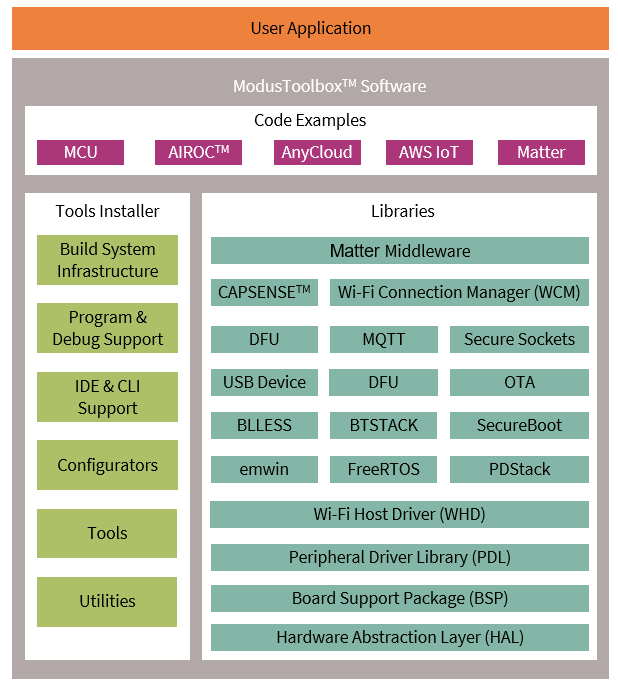
The ModusToolbox™ installer includes the design configurators and tools, and the build system infrastructure.
The build system infrastructure includes the new project creation wizard that can be run independent of the Eclipse IDE, the make infrastructure, and other tools.
All the ModusToolbox™ development flows depend on the provided low-level resources. These include:
- Board support packages (BSP) – A BSP is the layer of firmware containing board-specific drivers and other functions. The board support package is a set of libraries that provide APIs to initialize the board and provide access to board level peripherals. It includes low-level resources such as Peripheral Driver Library (PDL) for PSoC™ 6 family MCU and has macros for board peripherals. It uses the HAL to configure the board. Custom BSPs can be created to enable support for end-application boards. Refer to the "Board Support Packages" section in ModusToolbox™ user guide for more information.
Hardware Abstraction Layer (HAL) – HAL provides a high-level interface to configure and use hardware blocks on MCUs. It is a generic interface that can be used across multiple product families. The focus on ease-of-use and portability means that the HAL does not expose all the low-level peripheral functionality. The HAL wraps the lower-level drivers and provides a high-level interface to the MCU. The interface is abstracted to work on any MCU. This helps you write application firmware independent of the target MCU.
The HAL can be combined with platform-specific libraries within a single application. You can leverage the HAL's simpler and more generic interface for most of an application, even if one portion requires lower-level control.
- Peripheral Driver Library (PDL) – The PDL integrates the device header files, startup code, and peripheral drivers into a single package. The PDL supports the PSoC™ 6 family MCU device family. The drivers abstract the hardware functions into a set of easy-to-use APIs. These are fully documented in the PDL API Reference.
The PDL reduces the need to understand register usage and bit structures, thus easing software development for the extensive set of peripherals in the PSoC™ 6 family MCU series. You configure the driver for your application, and then use API calls to initialize and use the peripheral.
- Middleware (MW) - Extensive middleware libraries that provides specific capabilities to an application. All the middleware is delivered as libraries and via GitHub repositories. All libraries are constantly developed and the production-ready latest version is pushed via an integrated update system which the user can opt for.
PSoC™ 62S2 Wi-Fi BT Pioneer Kit
Overview of PSoC 62S2 Wi-Fi BT Pioneer Kit (CY8CKIT-062S2-43012)
The PSoC™ 62S2 Wi-Fi BT Pioneer Kit enables you to evaluate and develop your applications using the PSoC™ 6 Series MCU (hereafter called "PSoC™ 6 MCU") and CYW43012 WICED Wi-Fi/BT combo device. The PSoC™ 6 BLE Pioneer Board offers compatibility with Arduino™ shields. The board features a PSoC™ 6 MCU, and a CYW43012 Wi-Fi/Bluetooth combo module.
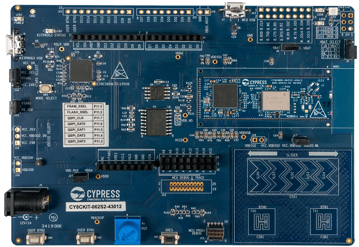
PSoC™ 6 MCU is Infineon's latest, ultra-low-power PSoC™ specifically designed for wearables and IoT products. PSoC™ 6 MCU is a true programmable embedded system-on-chip, integrating a 150-MHz Arm® Cortex®-M4 as the primary application processor, a 100-MHz Arm® Cortex®-M0+ that supports low-power operations, up to 2 MB Flash and 1 MB SRAM, Secure Digital Host Controller (SDHC) supporting SD/SDIO/eMMC interfaces, CAPSENSE™ touch-sensing, and programmable analog and digital peripherals that allow higher flexibility, in-field tuning of the design, and faster time-to-market.
Infineon's CYW43012 is a 28-nm, ultra-low-power device that supports single-stream, dual-band IEEE 802.11n-compliant Wi-Fi MAC/ baseband/radio and Bluetooth® 5.0 BR/EDR/LE. The WLAN section supports SDIO interface to the host MCU (PSoC™ 6 MCU), and the Bluetooth section supports high-speed 4-wire UART interface to the host MCU.
In addition, the board features an onboard programmer/debugger (KitProg3), a 512-Mbit Quad SPI NOR flash, a 4-Mbit Quad SPI F-RAM, a micro-B connector for USB device interface, a 5-segment CAPSENSE™ slider, two CAPSENSE™ buttons, a microSD card holder, an RGB LED, two user LEDs, one potentiometer, and two push buttons. The board supports operating voltages from 1.8 V to 3.3 V for PSoC™ 6 MCU.
Refer here for the PSoC™ 62S2 Wi-Fi BT Pioneer Kit guide.
Lock application with PSoC™ 62S2 Wi-Fi BT Pioneer Kit
This section demonstrates how to build a lock application on the PSoC™ 62S2 Wi-Fi BT Pioneer Kit
Methods for creating and building the Lock application
There are currently two ways to build and flash the Lock for Matter in a PSoC™ 6 device: standard GitHub repository (provided and maintained by CSA members) and Infineon's IDE ModusToolbox™. The user can avail any method to develop a Lock app but it is strongly suggested to use ModusToolbox™ to get full code and device support for the Matter Lock app or any other related app functionality. The following sections describe the methods available to develop the Lock app.
Connectedhomeip & Infineon GitHub repository
CHIP repository
CSA has its own repository for creating sample apps and change base code for Matter protocol development. There are different branches created for different levels of development. Every device-specific code will be available under 'Examples'. The user can choose any project available from Infineon and start developing for the same. In this scenario, the user should navigate to 'psoc6'
Visit this page to get started with Infineon's Lock App example on PSoC™ 6. Make sure to use the latest branch and updates (v1.0 onwards).
Infineon GitHub repository
Infineon has a separate GitHub repository along with the one on CSA, which includes the Lock app, Lighting app, all basic cluster apps, and a few apps that are under development.
Please navigate to this repository in Infineon GitHub page and proceed with the mentioned instructions. The latest tested (auto build and verify) code will be available in this repository.
Build process
The build process for both repositories is the same since the base device is PSoC™ 6.
User has to download the code from GitHub (clone) and fulfil all prerequisites mentioned.
These methods are mainly based on Linux and Mac environment; WSL or similar tools may be required if the user is working on a Windows system.
Run the mentioned commands in sequence in order to get the desired output.
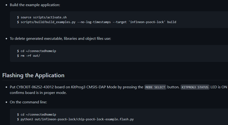
Few processes may fail due to the underlying system dependency. The user might need to install additional packages as instructed in the script output or in the GitHub process.
Flashing can also be done via the script available and uses no additional components like Jlink, Cypress Programmer etc. unless the user wants to debug the code (which is only possible via ModusToolbox™ Software).
ModusToolbox
Dependencies
Infineon's ModusToolbox™ is a complete package to get started with the PSoC™ 6 Matter Lock application. The Lock application supports ModusToolbox™ version 3.0 and above. The user can download the code from GitHub and use in ModusToolbox™ and/or use the existing sample Lock application in the ModusToolbox™ application creation process. All other desired configurators like GPIO, ADC, PWM, SPI, and many more are readily available for the same.
The user has the flexibility to add or remove any component suitable for the project using the inbuilt tools manager. Results and memory analysis of the built application can be viewed under different output window tabs in ModusToolbox™. Debugging is available by using additional tools like Jlink or using the inbuilt tool.
Project creation, build, and flash process
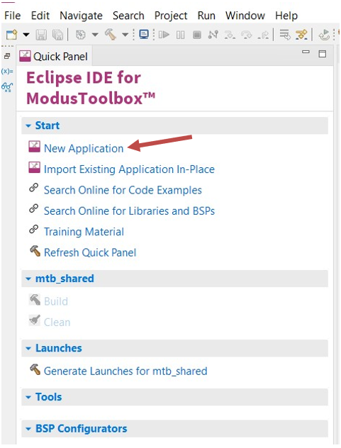
The user can create an application using the example creation mentioned in the ModusToolbox™ project creation process.
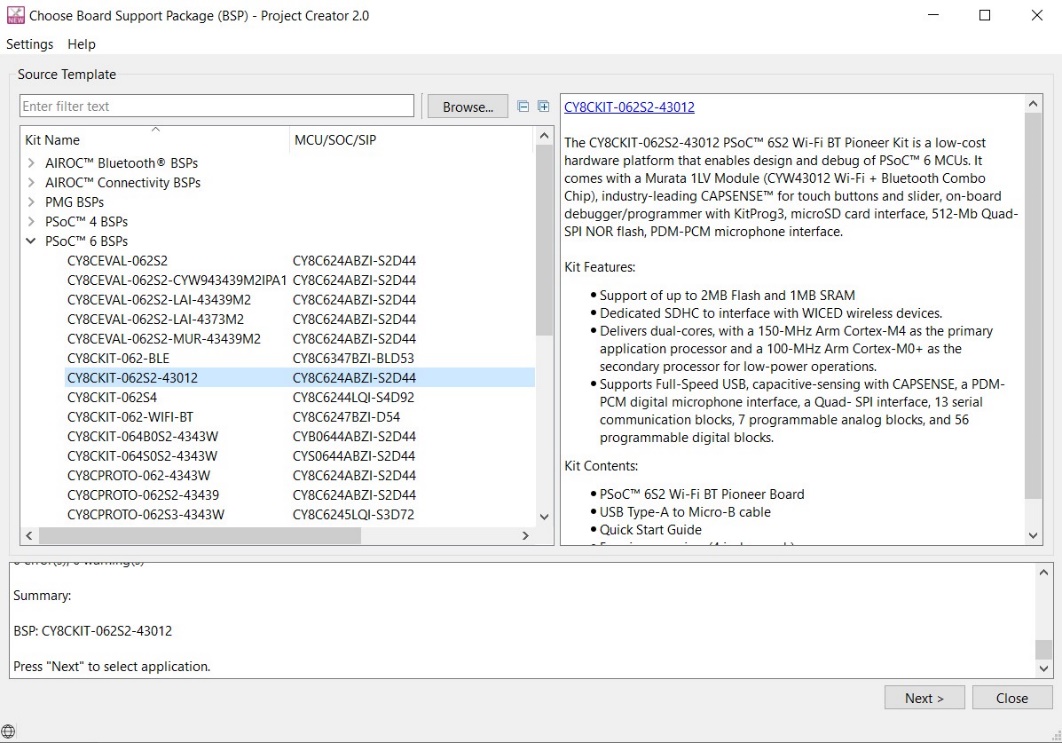
Please select BSP as which will be used in this sample Lock application (click Next).
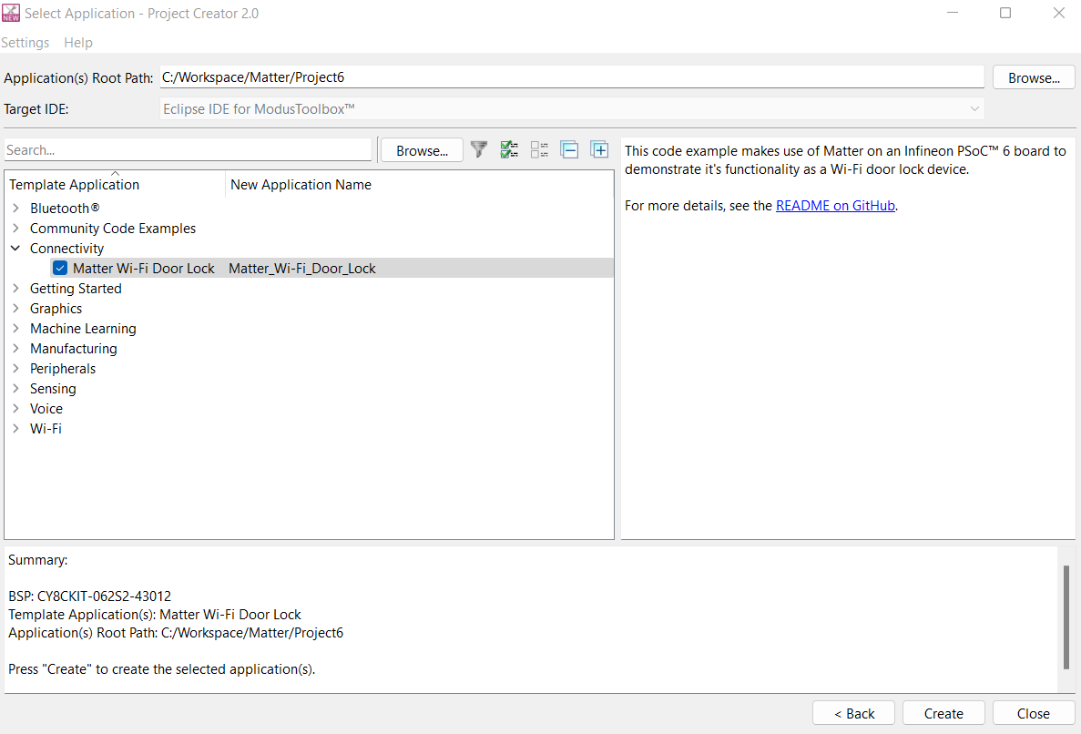
Under the Connectivity section, select "Matter Wi-Fi Door Lock" sample application and click Create.
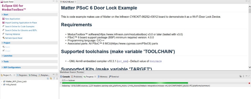
Project creation will take some time and the user can view the status in the progress window
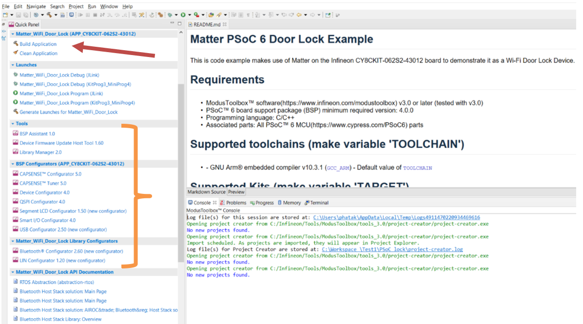
After successful creation, the user can modify the contents of the project, if required, by using tools like BSP assistant, Library Manager, CAPSENSE™ Configurator etc.The user can build the project using the "Build Application" GUI button.
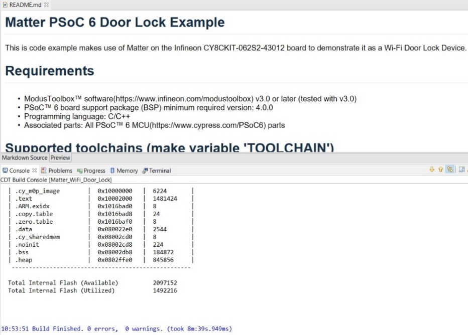
After successful build, the user can view the following output in the Console tab.
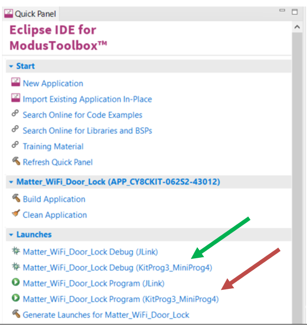
The user can flash the same using the following GUI button. This will initiate flashing via the inbuilt KitProg on the development board. The GUI button pointed by a green arrow can be used to debug the application by the inbuilt KitProg. There are options to flash and debug via standard JLINK.
After a successful flash process, the user can connect the board to the computer and run any serial terminal software (Putty, Tera-Term etc.) with the following parameters:
Baud: 115200, Parity: None, Stop bit: 1, Data bit: 8, COMxx. (xx is actual number of connected port).
- The user can view the logs and get boot and connection information from the connected serial terminal software and can use some information from it while connecting the device to the Matter ecosystem.
- USER BTN1 (SW2) on the CY8CKIT-062S2-43012 Wi-Fi BT Pioneer Kit can be used to toggle lock and unlock states. The Lock/Unlock status of door can be observed with LED9 on the board.
Ecosystem
Connecting PSoC™ 6 to any Matter ecosystem is the aim behind all the above processes. Many ecosystems in the market allow Matter devices to connect and control. As explained in section Overview of Matter connecting to matter involves certain secured steps like connection via Bluetooth® LE or NFC. The required connection data gets exchanged securely in these methods and PSoC™ 6 can be commissioned into the desired ecosystem.
Process to connect to ecosystem
Infineon's CY8CKIT-062S2-43012 kit has two wireless interfaces, Bluetooth® and Wi-Fi. Matter will work over Wi-Fi and Bluetooth® will be used to commission the device into the Matter network. Various ecosystem providers use a GUI system like mobile phones to scan nearby devices and commission into existing Matter network.
This process uses the phone's camera to scan the QR code, which initiates transactions on the Bluetooth® interface to securely send the Wi-Fi connection data to the device. Once the device is connected, Bluetooth® is no longer required and hence turned OFF. The other process requires scanning of the NFC tag, which is out of scope for this document.
Logs provided by the Infineon device contain the QR code hyperlink which, when entered in the browser, displays the QR code. As mentioned above, the user can scan the QR code and initiate the joining process, which may sometimes fail for one or more reasons. When connected, the user can seamlessly control and view the CY8CKIT-062S2-43012 device parameters in the GUI provided by the ecosystem. Similarly, the operational logs can be viewed during run-time on the console of the connected computer when the user controls the device.
References
Table 1 lists the application notes, datasheets, and technical reference manuals for PSoC™ 6 family MCU. Contact to obtain these documents.
| Documents | Description |
|---|---|
| Application notes | |
Describes how to set up a hardware environment | |
Describes how to get started with PSoC™ 6 on ModusToolbox™ Software | |
| Device datasheet | |
Describes the functions and electrical specifications of the target product. It also includes product-specific information such as address map, I/O map, pin assignment, alternate function pin assignments, interrupt source list, trigger group, peripheral clocks, faults, and bus masters. | |
| Technical reference manual | |
Describes details about the board, pins, operation and hardware configuration for the CY8CKIT-062S2-43012 PSoC™ 62S2 Wi-Fi BT Pioneer Kit | |
Glossary
This section lists the most commonly used terms that you might encounter while working with PSoC™ 6 family of devices.
Board support package (BSP): A BSP is the layer of firmware containing board-specific drivers and other functions. The board support package is a set of libraries that provide firmware APIs to initialize the board and provide access to board level peripherals.
Hardware Abstraction Layer (HAL): The HAL wraps the lower-level drivers (like MTB-PDL-CAT1) and provides a high-level interface to the MCU. The interface is abstracted to work on any MCU.
KitProg: Onboard programmer/debugger with USB-I2C and USB-UART bridge functionality. KitProg is integrated onto most PSoC™ 6 development kits.
MiniProg3/MiniProg4: Programming hardware for development that is used to program PSoC™ 6 devices on your custom board or PSoC™ 6 development kits that do not support a built-in programmer.
Personality: Expresses the configurability of a resource for a functionality. For example, the SCB resource can be configured to be an UART, SPI, or I2C personalities.
Middleware: Middleware is a set of firmware modules that provide specific capabilities to an application. Some middleware may provide network protocols (e.g., MQTT), and some may provide high-level software interfaces to device features (e.g., USB, audio).
Peripheral Driver Library (PDL): Simplifies software development for the PSoC™ 6 MCU architecture. The PDL reduces the need to understand register usage and bit structures, thus easing software development for the extensive set of peripherals available.
Revision history
| Document revision | Date | Description of changes |
|---|---|---|
** | 2023-02-22 | New application note. |
*A | 2023-07-03 | Updated link references. |
| *B | 2023-08-03 | Updated template; no content updated. |