AN219434 PSoC™ 6 MCU importing generated code into an IDE

About this document
Scope and purpose
AN219434 shows how to import the code generated by PSoC™ Creator, for the PSoC 6 MCU architecture, into your preferred integrated development environment. With this knowledge, you can combine the benefits of automatically generated code with your preferred IDE. High-level options are explained, with detailed instructions for each option.
Associated part family
PSoC 6 MCU
Associated code examples
Related application note
More code examples? We heard you.
To access an ever-growing list of hundreds of PSoC code examples, please visit our code examples web page. You can also explore the video training library here.
Introduction
A significant number of customers use the PSoC Creator tool as a hardware design platform but write application software in a different environment. There are several reasons why this might be. Your organization may have an established set of tools for developing products. You may wish to reuse legacy code built in another IDE. Or you may have a preferred development environment. This application note shows you how to use PSoC Creator generated code for the PSoC 6 MCU in such an IDE.
The PSoC 6 MCU is based on a dual-CPU Arm® Cortex®-M4 (CM4) and Cortex-M0+ (CM0+) Programmable System-on-Chip.
To enable firmware development for PSoC 6 MCU devices, Infineon provides two distinct development environments: one based on PSoC Creator, the other based on ModusToolbox™ v2.x software. Table 1 summarizes the key features for each workflow. See ModusToolbox™ Software Overview of the ModusToolbox™ User Guide for a high-level look at what’s available in ModusToolbox™ v2.x, and how it works.
| Feature | PSoC Creator | Eclipse IDE for ModusToolbox™ |
|---|---|---|
IDE Framework | Proprietary, not extensible | Eclipse-based, extensible |
Driver Library | Peripheral Driver Library (PDL) | psoc6pdl, psoc6hal library on GitHub |
Code Generation | Components (including Bluetooth® Low Energy and CAPSENSE™) | Configurators: device, CAPSENSE™, Bluetooth®, QSPI, SmartIO, SegLCD, USBDev |
Host OS | Windows | Windows, macOS, Linux |
Middleware | Bluetooth® Low Energy, dfu, em_eeprom, emWin, usb_dev, FreeRTOS | Extensive collection of libraries for multiple ecosystems. See PSoC™ 6 Middleware on GitHub. |
Post-processing tool | cymcuelftool (Windows, macOS, Linux) | Not required for most use cases; cymcuelftool is still supported |
This application note discusses the PSoC Creator environment and workflow. AN225588, Using ModusToolbox™ Software with a Third-Party IDE, discusses that environment and workflow.
The Peripheral Driver Library (PDL) is a software development kit (SDK) for PSoC 6 MCU devices. Your firmware uses PDL API function calls to configure, initialize, enable, and use a peripheral driver. The PDL also includes support for middleware such as Bluetooth® Low Energy, and real-time operating systems (RTOS). By design, the PDL is IDE-neutral.
However, PSoC Creator is fully integrated with the PDL. As a design environment, PSoC Creator helps you configure clocks, interrupts, pin assignments, and drivers using a friendly UI. To customize a driver, add a Component to the PSoC Creator design corresponding to the peripheral. Instead of writing configuration code, modify options in the Component. PSoC Creator then generates all the configuration code to set up the clocks, interrupts, pins, and custom drivers based on the design. When targeting a PSoC 6 MCU device, PSoC Creator generates code using the PDL. If you use the PDL without PSoC Creator, you must write all the configuration code for the design.
Generated code is a valuable resource because it handles a great deal of the complexity involved in setting up the firmware for a design. This application note explains how to use that generated code in any IDE. There is more than one way to do this. This note explores and explains your options. It also walks through an example to show you how it can be done. When you have finished this application note, you will know what your choices are, and how to integrate generated code into your preferred IDE.
Even if your circumstances prevent you from using generated code directly, all is not lost. This application note shows you how to use generated code to learn about the PDL.
To learn more about the PDL or PSoC Creator, see References for links to some of the available resources.
Integrating generated code
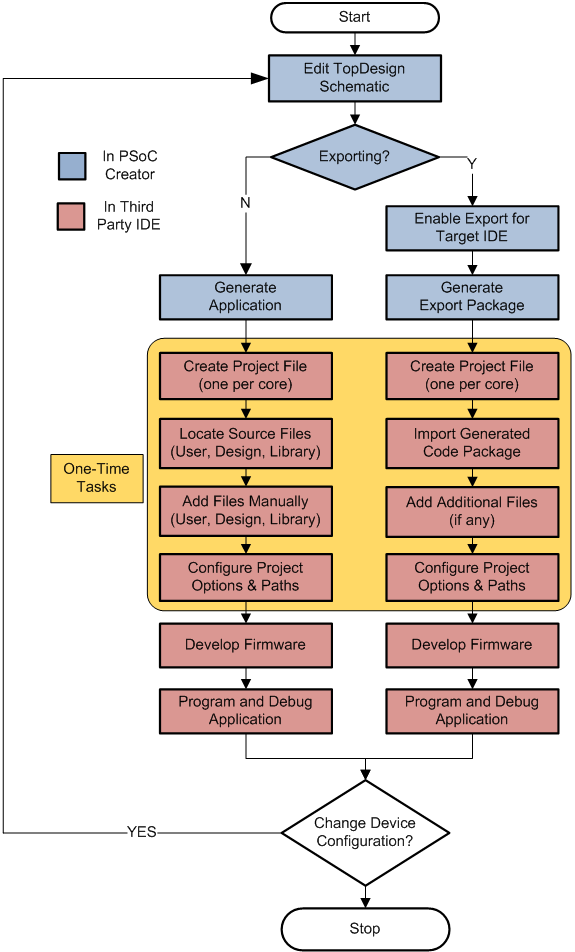
At a high level, there are two ways to integrate generated code into an IDE’s project file. The two paths are:
- Export code from PSoC Creator and import that code into an IDE
- Manually add generated source files to an IDE’s project
The flowchart in Figure 1 shows the tasks you perform for each path. This application note explains the one-time tasks noted in the flowchart. Based on your circumstances, one or the other path may be better for you.
The export path is available only for supported IDEs. See Exporting and importing generated code for details about this path. Supported IDEs include:
- IAR Embedded Workbench
- Keil µVision
- Eclipse-based IDEs
Manually importing code works for any IDE, including supported IDEs. For supported IDEs, additional resources are available that make the manual approach easier, including a fully configured project file, IDE-specific startup code, flash configuration files, and linker scripts. See Manually importing generated code for details about this path.
Advantages of generated code
If you use PSoC Creator to design and configure your
system, you gain significant benefits of generated code. All the necessary
configuration code is created for you. This code can be quite complex. For
example, the generated code in cyfitter_cfg.c initializes
all clocks, sets each clock’s source and divider, and enables all the clocks
in your design. It makes PDL API function calls to do so. This code is based
on the clock tree configuration in the PSoC Creator design.
The Bluetooth® Low Energy Component is another good example. The code to configure a Bluetooth® Low Energy Component is typically hundreds of lines long, declares a dozen configuration structures, and defines the values for more than 100 fields. PSoC Creator generates all this code automatically, based on the Bluetooth® Low Energy Component configuration in the design.
In addition to configuration code, PSoC Creator generates a simplified function API for each Component. The Component API is built on and uses the PDL API. This means that you can use the Component API instead of calling PDL functions directly. You can mix and match these APIs. They are consistent and compatible.
For example, to initialize, enable, and start a PWM using the PDL API, your code might look like this (ignoring errors):
Cy_TCPMW_PWM_Init (TCPWM1, counterNumber, &PWM_config);
Cy_TCPWM_Enable_Multiple (TCPWM1, whichCounters);
Cy_TCPWM_TriggerStart (TCPWM1, whichCounters);
By contrast, using the Component API, your code would look like this (for a TCPWM Component named MyPWM):
MyPWM_Start ();
The code generator implements the proper sequence of function calls to enable the
PWM. It also provides all the hardware-related parameters based on the
design and configuration in PSoC Creator. If you examine the generated code for the
MyPWM_Start() function, you find all three
PDL API calls implemented for you, and called in the correct sequence.
The generated code is primarily in C source and header files but may include assembler files and compiled binaries. If you add these generated files to an IDE project correctly, as described in this application note, iterative development is fully supported. When you modify the design in PSoC Creator and regenerate the application, the IDE recognizes that files have changed with no additional work required.
Limitations of generated code
PSoC Creator generates code compatible with the C99 standard. The compiler you use must support that standard. In addition, compilers can vary in subtle implementation details. There is always a chance that a particular compiler may handle some syntax in a non-standard way, but this is unusual.
The biggest limitation is that in most cases you cannot modify generated code. If you modify the code in a generated source file, the change is lost when you regenerate the code. Changes you make to generated code do not migrate upstream into the PSoC Creator design. If during the development cycle you discover that you need to modify the design, make the changes in PSoC Creator, and regenerate the application.
However, certain files generated by PSoC Creator are treated as user files. You can modify any user file without losing changes. See User files.
Tool compatibility
PSoC Creator and PSoC Programmer are proprietary tools built for Windows OS. When working with tools from other providers, you may encounter compatibility issues. For example, PSoC Creator adds proprietary information to the final hex file, and PSoC™ Programmer requires this information; other IDEs do not generate this information, so PSoC™ Programmer cannot use such a hex file.
ModusToolbox™ software and the newer Infineon Programmer do not have these issues.
Exporting and importing generated code
The export/import path is available for supported IDEs only. For supported IDEs, PSoC Creator provides an export package. Table 2 lists the export packages and which IDEs each package supports.
| Package | Supported IDE | Principal file | Path |
|---|---|---|---|
CMSIS Pack | Keil µVision v5 or later IAR Embedded Workbench v8.1 or later Eclipse-based IDEs that can import a CMSIS Pack | .pack file | Export/Pack |
Inter-Project Connection File (IPCF) | IAR Embedded Workbench | .ipcf file (one per CPU) | Export |
Makefile | GNU command-line tools | makefile | <project>.cydsn |
The export/import process is the same for all supported IDEs. After developing your design, take these steps:
- In PSoC Creator:
- Enable the creation of the export package
- Build your code (this generates the export package)
- In the 3rd party IDE:
- Create an empty project (one per CPU for multi-CPU devices)
- Import the package into the empty project
- If necessary, add additional files not included in the export package
- Configure project options
The details of the export/import process vary significantly among supported IDEs. This section gives you an understanding of how the process works. The exact steps and precise details are described in the PSoC Creator Help and PSoC™ Creator User Guide. This application note does not duplicate this information. You must use the documentation to successfully export and import a package into an IDE.
Enabling export for a target IDE
In PSoC Creator, use the menu command to open the project settings. Then, open the Target IDEs panel. Choose Generate for the export package you want to create. Figure 3 shows the CMSIS Pack option enabled. A CMSIS Pack is an IDE-agnostic delivery package for software components.
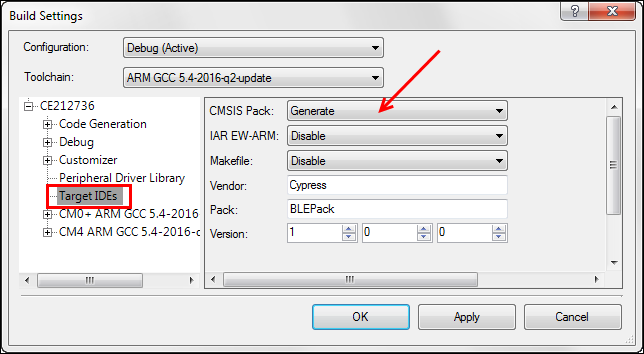
As an example of how the export process varies, the Vendor, Pack, and Version information shown in the figure are required only for the CMSIS Pack. IAR EW-ARM has different options.
See PSoC Creator documentation for details.
Generating the export package
After enabling the creation of a package, build your code. Use the PSoC Creator command. Note that the command does not generate the export package.
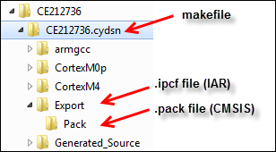
The contents of the Export folder vary per package. The package is a collection of files. PSoC Creator puts each package at the location listed in Table 2. When importing the package, navigate to that location to find the required files.
Importing the package
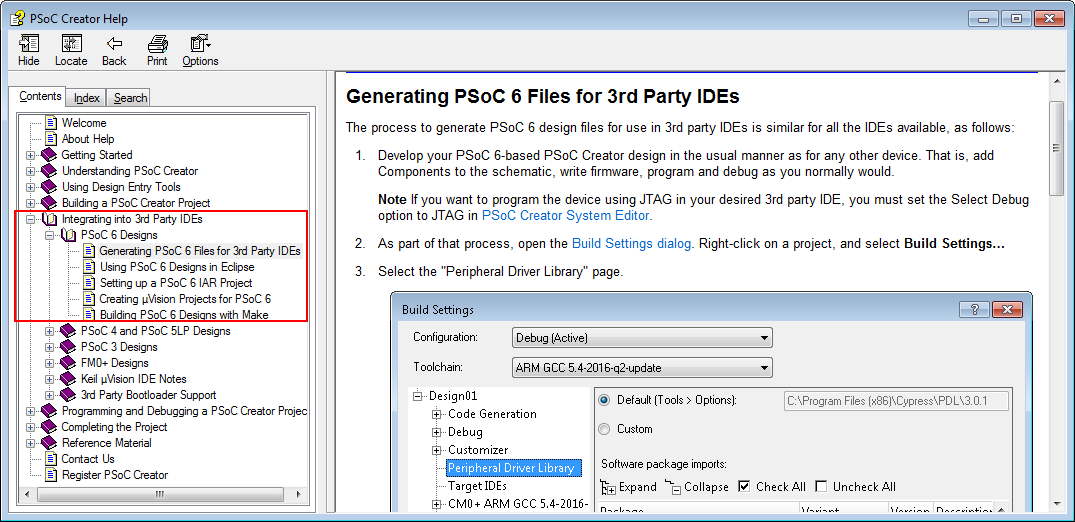
The import step is highly variable, based on the IDE and package. This section introduces you to the general tasks that you must perform to import a package. Refer to the PSoC Creator documentation for the precise steps and details. There is a help topic for each supported IDE, as shown in Figure 2.
In general, you perform these tasks:
- Create an empty project file (one per CPU for multi-CPU devices)
- Import generated code into each project file. Figure 4 shows where each package is located
- For a CMSIS Pack, install the Pack on your computer, and then import the Pack
- For IAR tools, establish a project connection using the .ipcf file
For GNU tools, use the generated makefile.
- In some cases, add additional files to each project file:
- For CMSIS Pack, you can create the CPU-specific main.c and linker files from templates
- For IAR tools, these files are included in the project automatically
- Set project options, which may include compiler, linker, and debugger settings
Different packages require that you set different project options. For example, the IPCF connection for IAR tools requires that you modify output folder names for the CM4 project, so they do not conflict with the CM0+ project. For the CMSIS Pack, you also specify include paths for header files, provide a path to the linker command file, and so on. PSoC Creator documentation provides all the details. Ensure that you are familiar with that documentation before exporting and importing generated code. See Appendix A - configuring an IDE project file for more information about project options.
Several files in a project are CPU- or IDE-specific, such as linker files, startup code, the makefile, and others. The correct files for each CPU and IDE are in the package. When you import the package, the correct files are included.
Supporting iterative development
After importing the generated code, you will likely encounter the need to change your design. Make the required change in the PSoC Creator project and rebuild the project. Do not modify files in the Generated_Source folder. Any change will be lost when you regenerate code.
When you rebuild the code in PSoC Creator, an updated package appears in the Export folder. The code generation process may have modified files, added new files, or removed files.
For the CMSIS Pack export, reinstall the Pack. Locate the pack file in the Export folder and double-click to install. The unzip dialog includes an alert that the Pack is already installed. Replace it. The IDE automatically recognizes the changes, including added or removed files. Rebuild your code in the IDE to update the executable.
The IAR inter-project connection file points to the PSoC Creator Generated_Source folder. The IDE automatically recognizes the changes, including added or removed files. There is no need to reconnect to the .ipcf file. Simply rebuild your code in the IDE to update the executable.
For a makefile, ensure that your build process uses the files in the Export folder. If it does, then a simple clean and build updates the executable using the new code.
Export/Import review
PSoC Creator documentation describes all the details. The import process begins with a new, empty project in the IDE.
For a CMSIS Pack, project setup for the IDE involves multiple steps. The Pack may be imported into a variety of IDEs, and each IDE is unique in how it handles build options, so you are required to set several options. This is a one-time task. Any change in the code (from a design change in PSoC Creator) is handled transparently. Just reinstall the Pack.
Inter-project connection is a protocol proprietary to the IAR tools. Because it is designed for one IDE, the project connection sets most options automatically. This is a very friendly process.
Manually importing generated code
Manual import works for any IDE, including supported IDEs that have an export/import process. For a non-supported IDE, manual import is the only option.
To begin, you must have generated code. In PSoC Creator, the Application command is sufficient. You do not need to compile the code. To manually import generated code, you:
- Create a project in the IDE (one for each CPU for a multi-CPU device)
- Locate and identify the generated files you need
- Add those files to the project
This section gives you the background required to understand what files PSoC Creator generates, where to find them, and which you need to add to your project. Manually importing generated code – an example walks you through the process in detail.
Creating a project file
This discussion assumes that you are familiar with your preferred IDE, that you know how to create and configure a project file, and that you have a project configured to work with each CPU on a multi-CPU PSoC 6 MCU device. See Appendix A - configuring an IDE project file for information on the kinds of options that must be configured.
You can start with a new, empty project file. However, Infineon provides a pre-configured template project for each supported IDE and PSoC 6 MCU CPU. There are CM4 and CM0+ projects for the µVision IDE, the IAR IDE, and the other supported IDEs. PDL template projects are fully described in the PDL v3.1 User Guide section titled Using PDL Template Projects. Template projects are located here: <PDL Install Folder>/devices/psoc6/templates.
Most build options in the template project are set correctly. Changes required when importing the generated code are discussed in this application note. In addition, the include paths in the template are project-relative. If you move the template project file to a different location, you must modify these paths. See Where to get PDL library files.
Locating and identifying source files
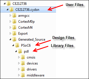
PSoC Creator generates three kinds of source files:
- User files – files you may modify
- Design files – files specific to the PSoC Creator design and Components
- Library files – files from the PDL
The following sections describe each kind of source file in detail.
PSoC Creator puts these files in various folders inside the <project>.cydsn folder. This application note refers to this location simply as the cydsn folder. Figure 5 shows the folder tree and locations for generated source files.
User files
A user file is one that you may change based on the requirements of your design. PSoC Creator generates the file (which may be functionally empty), and never changes it. These are the key concepts to understand about user files:
- The files are created automatically when you create a PSoC Creator project and generate the application for the first time
- PSoC Creator does not change or replace these files once they are created. Therefore, you can modify these files as required for your design
- All files are local copies, so changes have no impact on other projects or the installed PDL library
- For a multi-CPU device, add CPU-specific files to the correct project in your IDE; add shared files to the project for each CPU
You do not need every file; some are specific to a particular tool chain.
Table 3 lists common user files. User files are at the top level of the cydsn folder (except for the startup code, as noted in the table). Some file names vary based on the device. The table uses the psoc63 series as the example. Some files are CPU-specific. Startup code and linker files are also IDE-specific. Use the appropriate files for your project. Disregard the others. If you use an unsupported IDE, provide equivalent files compatible with the IDE.
Depending upon your design, there may be additional user files. Any source file at the top level of the cydsn folder is a user file and should be added to one or both projects, depending on whether the file is CPU-specific.
| File | Action | Source | Usage | Notes |
|---|---|---|---|---|
main_cm0p.cmain_cm4.c | Add to project1or provide your own. | Generated | Required | PSoC Creator puts the user files at the top level of the cydsn folder |
cyapicallbacks.h | Provide the path to the header. | Generated | Required | An empty file for the user to implement macro callbacks (see PSoC Creator Help topic Writing Code) |
system_psoc6.h | Provide the path to the header. | Copied from PDL | Required | Contains user-definable clock configuration macros |
system_psoc6_cm4.csystem_psoc6_cm0plus.c | Add to the project. | Copied from PDL | Required | Per-CPU; system configuration code |
| startup_psoc6_01_cm4.s startup_psoc6_01_cm0plus.s (IAR) | Add to the project. For an unsupported IDE, provide a startup file. | Copied from PDL | Use the file for your IDE | Per-series, CPU, and IDE; startup code is located in .cydsn/<IDE>/startup |
| startup_psoc6_01_cm4.s startup_psoc6_01_cm0plus.s (MDK) | ||||
| startup_psoc6_01_cm4.S startup_psoc6_01_cm0plus.S (GCC) | ||||
cy8c6xx7_cm4_dual.icf cy8c6xx7_cm0plus.icf | Set project options to use the CPU-specific linker file. For an unsupported IDE, provide a linker file. | Copied from PDL | Use the file for your IDE | Per-series, CPU, and IDE;linker command file |
cy8c6xx7_cm4_dual.scat cy8c6xx7_cm0plus.scat | ||||
cy8c6xx7_cm4_dual.ld cy8c6xx7_cm0plus.ld |
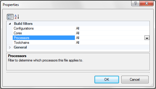
While some files are CPU-specific, some are used by each CPU in a multi-CPU device. The file system_psoc6.h is a good example. Each CPU uses the same file to set up CPU clocks based on the user-definable clock configuration macros. When manually importing a shared file into an IDE, the file must be added to the project for each CPU. If in doubt, right-click a file in the PSoC Creator Workspace Explorer pane and examine its properties to see which CPU toolchain uses the file.
1 Add CPU-specific files to the project for the corresponding CPU.
Design files
PSoC Creator automatically generates several files that are specific to your design. In some cases, these files are specific to a supported IDE as well. All design files are in this folder: cydsn/Generated_Source/PSoC6.
Design files are described in PSoC Creator Help in the Building a Creator Project > Generated Files (PSoC 6) topic. The design files also include a source and header file for each Component in the design. If a Component is based on a Universal Digital Block (UDB), all the files required to configure and use the Component are among the design files.
These are the key concepts to understand about design files:
- PSoC Creator may change these files any time you generate the application
- Do not modify these files; any change will be lost when you generate the application
- Component-specific files are named <Component Name>.h and <Component Name>.c
- Some files are optional and/or IDE-specific (see Table 4)
Most design files are shared files. For a multi-CPU device, add shared files to the project for each CPU. Any CPU-specific file identifies the CPU in the file name.
Table 4 lists design files, and the action required to use a file in your project
| File | Action | Usage | Notes |
|---|---|---|---|
project.h | Provide path to header2. | Required | Includes all headers listed in this table |
<Component Name>.c/h | Add source file to project.Provide path to header. | Required | Code for component-specific APIs. Header file included by project.h |
cyfitter.h | Provide path to header. | Required |
|
cyfitter_cfg.c/h | Add source file to the project.Provide path to header. | Required | Code to configure the device before reaching |
cyfitter_gpio.h | Provide path to header. | Required |
|
cyfitter_sysint.h | Provide path to header. | Required |
|
cyfitter_sysint_cfg.c/h | Add source file to project.Provide path to header. | Required | Code to configure system interrupts |
cymetadata.c | Add to project. | Required | Defines all extra memory spaces that need to be included. |
cydevice_trm.h | Provide path to header. | Required | Defines all addresses in the configuration space of the device |
cydisabledsheets.h | Provide path to header. | Required |
|
cydevicegnu_trm.inc | Include in your assembler code if required. | Optional | Per IDE; defines all addresses in the configuration space of the device for the assembler |
cydeviceiar_trm.inc | |||
cydevicerv_trm.inc | |||
cycodeshareexport.ld | Set project options to use the script if required. | Optional | Per-IDE; linker script to export or import symbols to/from a different application; typically, empty |
cycodeshareimport.ld | |||
cycodeshareimport.scat |
The default main_cm0p.c and main_cm4.c files include project.h. The project.h file in turn includes all other required headers among the design files. If you provide your own main.c files, ensure that you include project.h.
Although cydisabledsheets.h is typically empty, there is no
easy way to remove it from the project. It is included by
project.h. If you delete the #include statement,
that statement reappears the next time you generate code.
Library files
Library files are copies of files from the PDL installation. PSoC Creator automatically copies the required files into subfolders of the cydsn/Generated_Source/PSoC6/pdl folder. See the PDL v3.1 User Guide to learn about the PDL.
These are the key concepts to understand about library files:
- Only required files are copied, not the entire PDL
- Some files may be assembler source files, or precompiled binaries
- PSoC Creator never modifies library files
- Do not modify these files; any change will be lost when you generate the application
- Most library files are shared files. For a multi-CPU device, add shared files to the project for each CPU. Any CPU-specific file identifies the CPU in the file name
What library files appear in the pdl folder tree depends upon your design. Table 5 lists the key locations in the tree, what is in each folder, and how to use those files in a project.
| Path/Folder | Action | Notes |
|---|---|---|
pdl/cmsis/include | Provide a path to this folder. | CMSIS header files |
pdl/devices/psoc6/include/ip | Provide a path to this folder. | Header files for IP blocks on the device |
pdl/devices/psoc6/include | Provide a path to this folder. | Device-specific header files |
pdl/drivers/peripheral | Add source files to project.Provide a path to this folder and all the subfolders. | Source and header files for peripheral drivers used in the design |
pdl/middleware | Add source files to project.Provide a path to this folder. | Source and header files for the middleware used in the project; do not add paths to subfolders. |
#include statement. Adding files to a project
As you identify the files you need, add them to the IDE’s project file. Each IDE has its own way of adding a file to a project. For example, the IDE may support drag and drop, or adding a batch of files through the IDE’s user interface.
There are three key principles to keep in mind as you add the files:
First, add each file directly from its location in the PSoC Creator cydsn folder. This is critical to support iterative development. If you change the design in PSoC Creator, some generated files will change. By pointing the IDE project at the files in the cydsn folder, you ensure that any changes to the files appear in your project.
Second, some files are CPU-specific. Add CPU-specific files to the corresponding project. For a multi-CPU device, add shared files to both projects. The file name for a CPU-specific file identifies the CPU.
Third, you must add include paths so that the preprocessor can locate required header files. The good news is that most headers are grouped into single folders. Some developers prefer to add the header files to a project for easy access to the file. Even if you do, most IDEs still require that you add include paths for the preprocessor.
Where to get PDL user files
Some PSoC Creator generated user files start as copies of default PDL files. Do not use the original PDL files. Use the generated copies in the cydsn folder.
User files may be changed by the user. If you change the original PDL file, that change affects any other project using that file. Best practice dictates that you use the copies in the cydsn folder. See User files.
If you start with a PDL template project, you should:
- Remove the user files from the project (they are the originals from the PDL installation)
- Add the same files back to the project from the cydsn folder
- Delete the project-relative path to the /include folder. It typically looks something like this in an IDE: ../../../include
- Add a path to the cydsn folder where PSoC Creator puts the user files
If you start with an empty project, add the files from the cydsn folder, and set a path to this folder.
Where to get PDL library files
Library files are copies of the PDL files and should never be changed by the user. Add these files from the cydsn/Generated_Source/PSoC6/pdl folder. PSoC Creator copies only the library files you need.
A PDL template project has preset paths to PDL header files that point to original files in the PDL installation, not the generated code. If you start with a PDL template project, you should:
- Delete any project-relative path to the PDL installation
- Replace with paths to the same locations in the cydsn/Generated_Source/PSoC6/pdl folder
The preset paths may include /cmsis/include,/ip,/drivers/peripheral etc.
Supporting iterative development
After you import the generated code and set project options so that the project builds in the IDE, you will encounter the need to change your design. Importing files into an IDE involves some effort, but this is a one-time task.
The key requirement to support iterative development is simple: import the files from the cydsn folder. After making design changes in the PSoC Creator project, build the code. Depending on the changes, the code generation process may modify, add, or remove files.
Modified files
PSoC Creator modifies only design files. If you add the generated code from the cydsn folder to your project file, the next build will use the latest version of the files. Rebuild your code in the IDE to update the executable. No additional work is required.
Added or removed files
Add any new file (either design file or library file) to your project. Similarly, if a file is no longer necessary, you can remove it from your project file. Then rebuild your code in the IDE to update the executable.
Manual import review
While this section provides significant details about PSoC Creator generated code, the process of manually importing generated code into an IDE project file is quite simple:
- Identify the generated files you need (user, design, and library)
- Add them to the project file (from their location in the cydsn folder)
- Set include paths to find the header files
Manually importing generated code – an example
This section walks you through the process of importing generated code from a relatively complex code example. Because every project and IDE is different, this example is not a series of precise steps and directions.
To gain maximum value from this walk-through, you should download, install, and build (using PSoC Creator) the CE21736 code example. Create a new empty project in an IDE. Then explore the contents of the PSoC Creator cydsn folder as you import the code.
A single example cannot cover all eventualities. Among the variables are the choice of project file (template or empty), which IDE to use (many possibilities), the nature of the firmware itself, and the particulars of your build environment.
The information in Manually importing generated code should enable you to make informed decisions for your circumstances. Given the broad number of choices, each of which would result in a different example, this walk-through is based on the following options:
- An empty project file – This approach supports any IDE
- Keil µVision tools – Although this is a supported IDE, this choice provides a contrast to allow users to determine which path is better for their circumstances, CMSIS Pack or manual import
- CE212736 as the example project – because it provides a rich domain for exploring the choices you face when importing code
- CE212736 – PSoC 6 MCU with Bluetooth® Low Energy Connectivity uses the Bluetooth® Low Energy stack, assembler source code, and precompiled binary files, as well as several peripheral drivers. This walk-through does not run the code example on hardware or explain its functionality
This walk-through imports code into a CM4 project. For a multi-CPU device, you build both CM0+ and CM4 projects.
After you complete the design and build the PSoC Creator project, the process is identical for each CPU:
- Set up the IDE project file
- Add files to the project
- Set include paths
- Build the project in the IDE
Complete the design and generate application files
You must be able to successfully generate the application in PSoC Creator before you import to an IDE. Figure 7 shows the PSoC Creator workspace explorer after generating the application files for the CE212736 project.
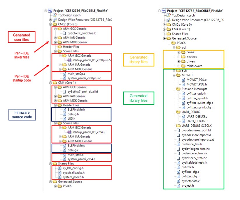
The Generated_Source item in the Workspace Explorer pane contains all the files that are in the project’s cydsn/Generated_Source folder. This design uses a Bluetooth® Low Energy Component, a multi-counter watchdog timer (MCWDT), and a UART to print debug messages to a terminal window. It also has pins to control LEDs and sets up system interrupts.
Because this is a complete code example, the project also contains the firmware source code to implement the example. If you prefer to develop code in another IDE, typically you would create these files in the IDE, not in PSoC Creator.
Set up the IDE project file
Create a new project. Typically, the IDE requires that you specify the target device. There are likely to be additional steps in an IDE’s project creation process.
For example, in Keil µVision tools, choose Project > New µVision Project. Specify the target device. You can download the PSoC6_DFP pack from the Infineon GitHub repository and install the pack. The pack provides PSoC 6 device support in Keil µVision and other IDEs that support CMSIS packs. Using the right device will automatically set the memory address range, programming algorithm, and so on. If the device is not available, or if you are using an IDE that does not support CMSIS packs, you can start by selecting the right Arm® CPU for the project and manually provide the required details specific to the device.
After specifying the device, pick software packs. Figure 8 shows an example. For this walk-through, no software pack is required.

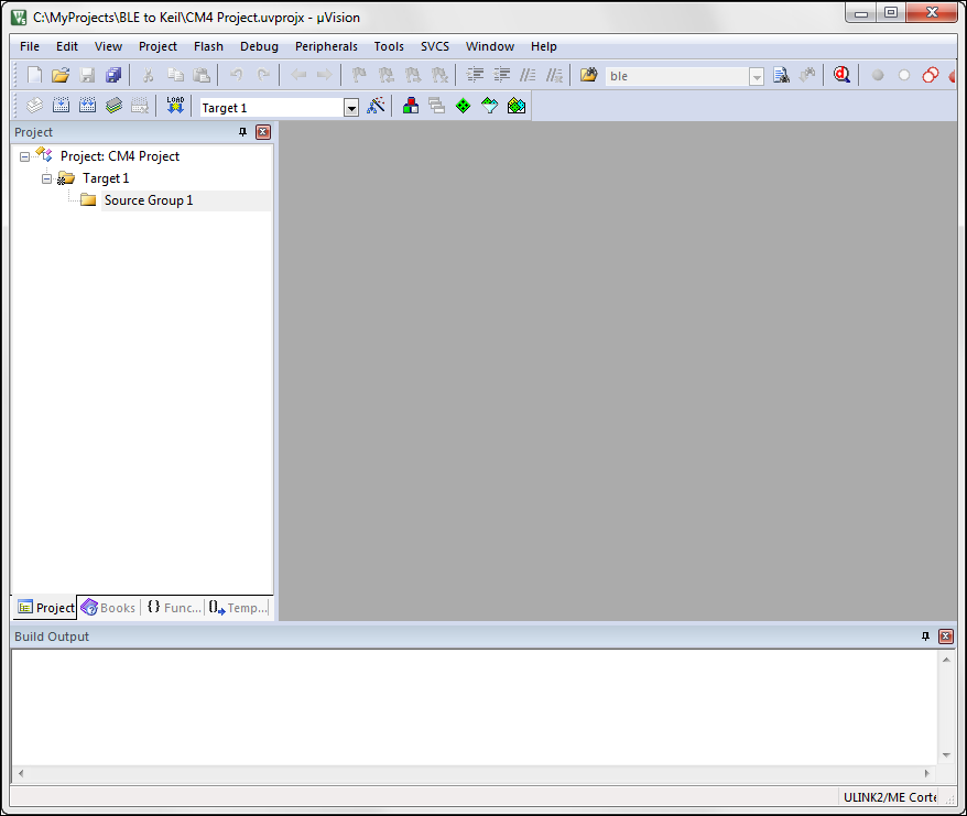
When done, an empty project appears, as shown in Figure 9. For this example, we named the project as "CM4 Project". When importing code for a multi-CPU device, you need a project for each CPU.
Add files to the project
Identify the files you need and add them to your project. Each IDE has its own workflow for adding files.
An IDE typically has a file explorer pane of some kind. You can add or remove groups within the project to organize your files as you see fit. The guidance in this section is merely that: guidance. You may prefer another organizational scheme. Figure 10 shows the group structure used in this walk-through. It matches the kinds of files PSoC Creator generates, with one exception. Because the Bluetooth® Low Energy stack is a large collection of files, this example puts them in a dedicated group.
Add firmware files
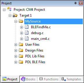
Because this walk-through imports a fully-functional code example, we import the firmware files into the MySource group, as shown in Figure 11. The firmware files are all in the cydsn folder for the PSoC Creator project. In your own work, you would create your own firmware files, and organize them in the project file as you see fit.
Add user files
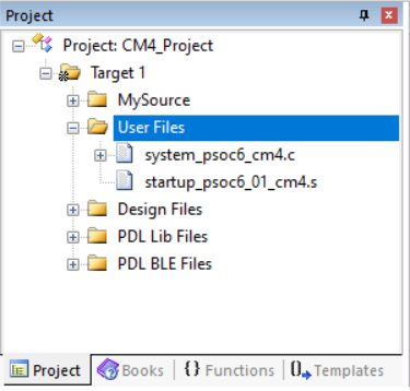
User files are generated by PSoC Creator, but you can change these files. User files are located at the top level of the cydsn folder. The startup code is in an IDE-specific folder. See User files. In this case, the user files are:
- A system configuration file (CPU-specific)
- A startup file (IDE- and CPU-specific)
Figure 12 shows the user files in the project explorer.
Note: The startup file is IDE-specific assembler source code. The generated code includes the startup code for all supported IDEs. Use the file you need. If you are working with an unsupported IDE, provide your own startup code.
Add design files
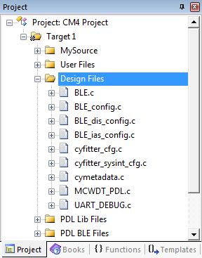
Design files are the source and header files generated by PSoC Creator specific to your system design and its Components. See Design files. Design files are in the cydsn/Generated_Source/PSoC6 folder.
Figure 13 shows the design files for this project added to the µVision project. These include the cyfitter and cymetadata files, as well as the Component-specific source files for the Bluetooth® Low Energy, MCWDT, and UART Components.
Add PDL library files
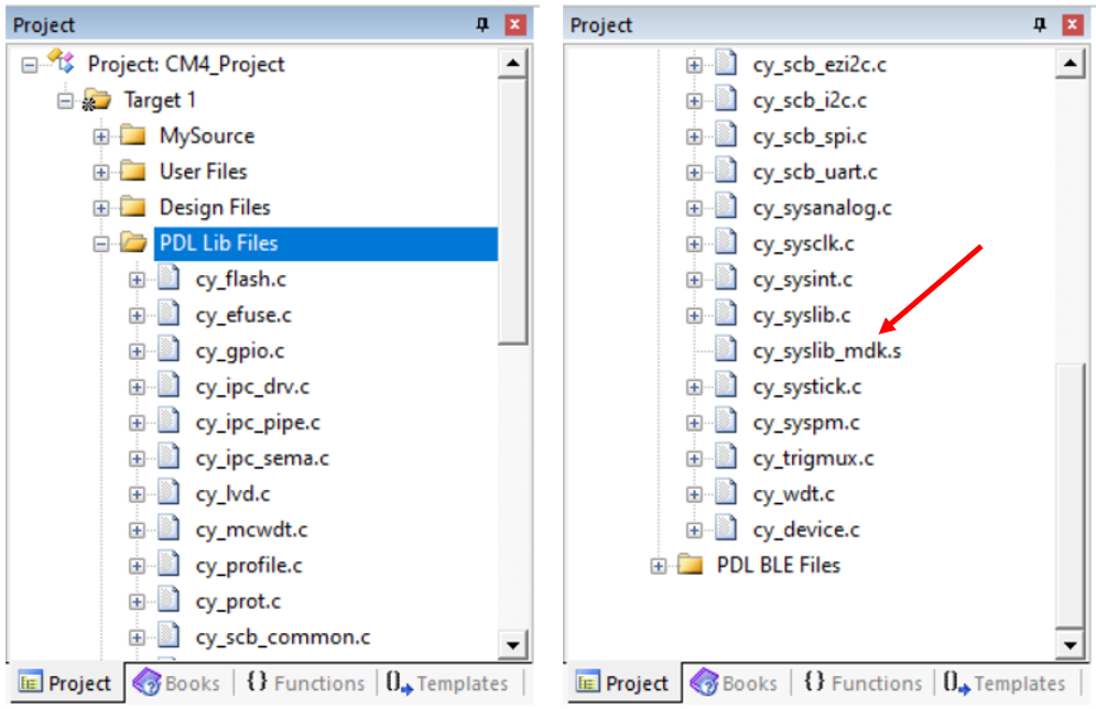
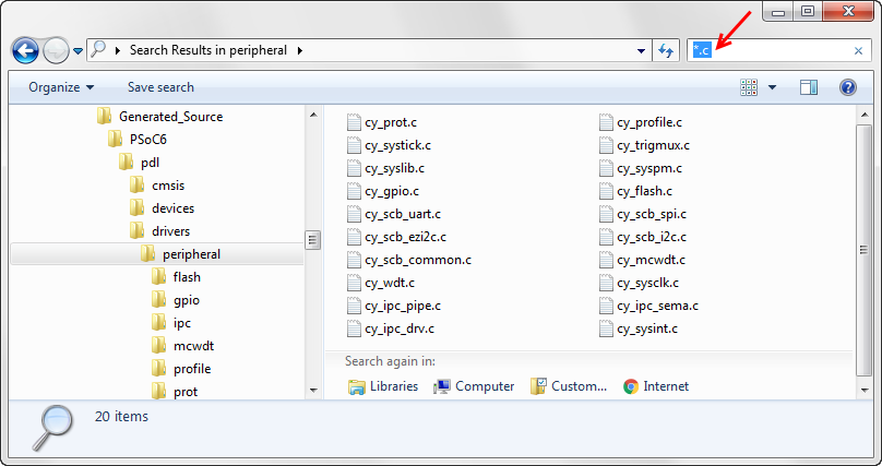
Library files are copied from the PDL installation. See Library files. Based on your design, PSoC Creator copies required files into the cydsn/Generated_Source/PSoC6/pdl/drivers/peripheral folder. Figure 13 shows the peripheral driver files for this project added to the IDE.
Add Bluetooth Low Energy library files
The final collection of files used in this design is the Bluetooth® Low Energy stack. The generated code is located at cydsn/Generated_Source/PSoC6/pdl/middleware/ble folder. Some parts of the Bluetooth® Low Energy stack are provided as CPU-specific binary libraries, not source code. All required source files and binary libraries must be added to the project.
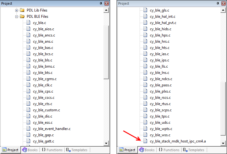
Note: When repeating this process for the CM0+ project, add libraries specific to that CPU.
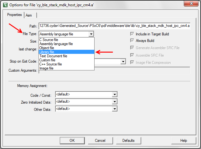
Note: An IDE may treat the library file as an assembler source file rather than a library, which causes build errors. The IDE may have a property to control this. For example, Figure 17 shows the file properties dialog for the µVision IDE.
Set include paths
The IDE’s build system must locate all necessary header files. Some developers prefer to add header files directly to the project explorer for ease of access. However, this typically does not set include paths for the IDE.
Each IDE has its own way of setting include paths. This example assumes that you know how to add include paths in your preferred IDE. The goal of this section is to show you what paths you need to add, not how to add them.
In the µVision IDE, you add paths in the target options C/C++ panel in the Include Paths item.
Set a path to user files
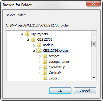
All header files for the PSoC Creator generated user files are in the cydsn folder. The path of course depends upon where you put the PSoC Creator project. In this example, the path for the CE212736 project could look like this:
C:/MyProjects/CE212736/CE212736.cydsn
Figure 18 shows setting that path in the µVision IDE.
Set a path to design files
All header files for the PSoC Creator generated design files are in the cydsn/Generated_Source/PSoC6 folder. In this example, the path for the CE212736 project could look like this:
C:/MyProjects/CE212736/CE212736.cydsn/Generated_Source/PSoC6
Figure 19 shows setting that path in the µVision IDE.
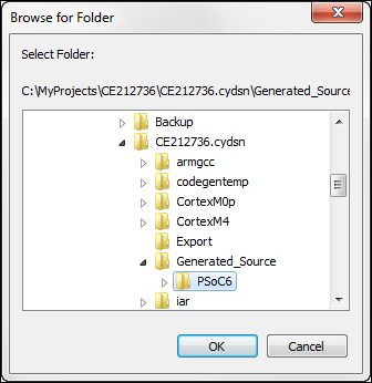
Set a path to peripheral folder (driver files)
Each peripheral driver has its own subfolder, and each peripheral driver has a header file that needs to be included in the project. So, the path to each driver subfolder needs to be added as part of the Include Paths. For example, the path to be added to include the flash driver header file in this project would be:
C:/MyProjects/CE212736/CE212736.cydsn/Generated_Source/PSoC6/pdl/drivers/peripheral/flash
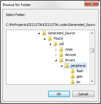
Along with this, the path to the peripheral folder that contains all driver subfolders should also be added. The peripheral folder path for the CE212736 project would be:
C:/MyProjects/CE212736/CE212736.cydsn/Generated_Source/PSoC6/pdl/drivers/peripheral
Figure 20 shows the setting of the peripheral folder path in the µVision IDE.
Set a path to the middleware folder (Bluetooth Low Energy stack)
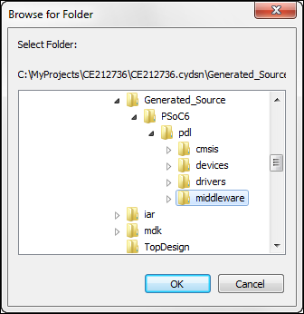
Although the Bluetooth® Low Energy stack is in a subfolder, the source code provides the path to include any header file within the middleware folder. As a result, a single path works for all locations in this folder tree. In this example, the path for the CE212736 project could look like this:
C:/MyProjects/CE212736/CE212736.cydsn/Generated_Source/PSoC6/pdl/middleware
Figure 21 shows setting that path in the µVision IDE.
Set other required paths
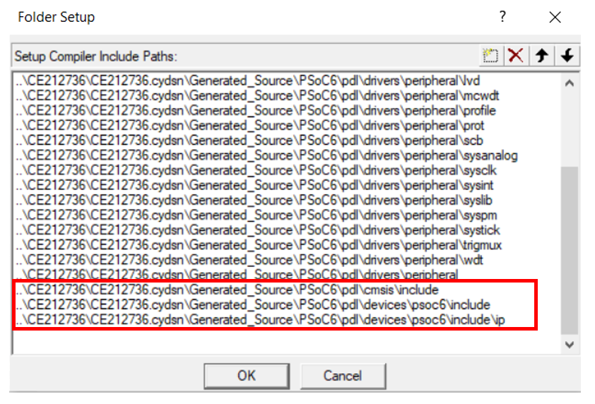
There are other header files that must be included for a successful build. PSoC Creator provides copies of these header files in the cydsn/Generated_Source/PSoC6/pdl folder:
- CMSIS header files: cydsn/Generated_Source/PSoC6/pdl/cmsis/include
- The ip header files: cydsn/Generated_Source/PSoC6/pdl/devices/psoc6/include/ip
Series-specific header files: cydsn/Generated_Source/PSoC6/pdl/devices/psoc6/include
Figure 22 shows these three paths set in the µVision IDE, pointing to the generated code.
Build the project in the IDE
Before compiling the code, you must configure all options required for your application to build successfully. This application note is about how to import generated code into an IDE, not about how to configure a project in any given IDE. However, Appendix A - configuring an IDE project file provides additional background.
With all the required files added and all paths set correctly, build your project. It should build successfully. You may encounter warnings or errors. Each IDE has a unique interface, as well as unique options, default settings, and warning and error messages. Because of the variability in IDEs, this application note cannot provide detailed guidance on handling errors. Your familiarity with your IDE will go a long way towards resolving any issues you encounter.
Related to importing code, however, there are typically three kinds of errors you may encounter.
If a “file not found” error occurs for a header file, locate the actual file in your file system. Ensure that there is an include path for that file.
If a function or symbol is undefined, make sure all user, design, and library files have been added to the project, and that any header file that declares the symbol is found. For example, failing to include binary libraries causes this kind of error.
Even when all files and paths are correct, you may get a cascade of compiler or linker errors. There may be a setting in your project not configured correctly. For example, if the compiler in the IDE does not default to supporting the C99 standard, ensure that support is enabled.
Example review
This section provided an example of importing code manually into an IDE. While a single example cannot cover all situations, the tasks are straightforward:
- Create and configure a project file in the IDE, one per CPU for a multi-CPU device. Or, start with a PDL template project
- Add the required PSoC Creator generated files to the project file (for a multi-CPU device, do this for each CPU)
- Set include paths for those files
PDL template projects provide flash configuration, linker, and startup files. If you prefer an unsupported IDE, use those as a reference. The IDE-specific files are located here: <PDL Install Folder>/devices/psoc6.
Finally, this application note teaches you the basic principles of importing code, such as what files exist, where to find them, and how to use them. You will need to apply this knowledge to your circumstances.
Summary
Writing software for a dual-CPU embedded system, like the PSoC 6 MCU, can be a daunting task. PSoC Creator simplifies that process. You create and configure a design using a friendly UI. PSoC Creator generates all the code required to implement that design, literally at the click of a button. You focus on real value, creating firmware on top of that generated code.
You can develop that firmware entirely in PSoC Creator, but many developers and organizations have a preferred development system.
This application note showed you how to use PSoC Creator generated code in a third-party IDE: either a supported IDE via export and import, or any IDE via manually importing the required files. You learned about the different kinds of generated files, where to find the files, and how to add them to the IDE’s project.
The knowledge contained in this application note enables you to combine the best of both worlds: high-quality generated code to shorten development time, and your preferred IDE.
References
| Application notes | |
|---|---|
AN210781 – Getting Started with PSoC 6 MCU with Bluetooth® Low Energy (BLE) Connectivity | Describes PSoC 6 MCU with Bluetooth® Low Energy Connectivity devices and how to build your first PSoC Creator project |
AN215656 – PSoC 6 MCU: Dual-Core CPU System Design | Describes the dual-core CPU architecture in PSoC™ 6 MCU, and shows how to build a simple dual-CPU design |
AN225588 – PSoC 6 MCU Importing Generated Code into an IDE | Describes the analogous process for ModusToolbox™ software and configurators, rather than the PDL and PSoC Creator |
| PSoC 6 MCU | |
| PSoC™ 6 MCU home page | Provides access to all PSoC 6 MCU resources |
| PSoC™ 6 MCU community | Discusses PSoC 6 MCU questions |
Peripheral Driver Library (documents installed with the PDL) | |
Peripheral Driver Library v3.0 User Guide | Overview of the library and how to use it |
Peripheral Driver Library API Reference | Detailed technical reference for the API |
| PSoC™ Creator | |
| PSoC™ Creator Product Page | Access to downloads, training, components, and more |
| PSoC™ Creator Quick Start Guide | Get up and running quickly |
| PSoC™ Creator User Guide | Comprehensive manual |
| Development kit documentation | |
| CY8CKIT-062-BLE PSoC™ 6 BLE Pioneer Kit | |
Appendix A - configuring an IDE project file
For the code to build successfully, you must configure the IDE project file with settings for various options. Because each IDE has a unique UI and default settings, how to configure an empty project for any particular IDE is beyond the scope of this application note. However, a general concept of what you need to configure is invaluable. Armed with that knowledge, you can locate and set the appropriate options in the IDE.
Table 6 lists several options required to configure an IDE project file. For any given IDE, there may be additional options. The default setting for any option may already be set correctly.
| Type | Option | Notes |
|---|---|---|
Device | Target | If the IDE supports a particular device, select the device. This typically sets other device-dependent options automatically. If the device is not listed in the IDE, choose a generic Cortex® M4 or M0+ device, and ensure that all device-dependent options are set correctly. |
Compiler | C99 Support | Enable support for the C99 standard. |
Floating Point | Enable floating point support for the CM4 CPU. | |
Optimizations | Set the compiler optimization level appropriate for your build. | |
Debugging | Generate debug information for a debug build. | |
Include Paths | Set include paths. This application note discusses all paths related to generated code. | |
Debug Symbol | Conditionally-compiled PDL code requires a debug symbol be defined. For a debug build, define DEBUG. For a non-debug build, define NDEBUG. | |
Device Symbol | Conditionally-compiled device-specific PDL code requires the correct symbol be defined. This symbol controls which device-specific header file is used for the build. See cy_device_headers.h. | |
Linker | Command File | Specify the path to the linker script. The PDL provides linker files for supported IDEs. If the IDE has device-specific support, this may be set automatically. |
Other Settings | Set other linker options for your build. For example, generate a linker map file, output debug information, generate a log file, and so forth. | |
Debugger | Debug Connection | Specify a supported debug connection (probe), such as J-Link or CMSIS-DAP. |
Connection Settings | Based on your debug connection, specify various connection settings such as reset options, connection speed, cache options, download options, and so forth. | |
Memory Configuration | Specify memory regions for the device. If the IDE has device-specific support, this may be set automatically. | |
Register Description | The PDL provides a system view description (SVD) file for register-level debug information. If the IDE has device-specific support, this may be set automatically. | |
Flashloader | Specify the flashloader to use for downloading the executable to the device. If the IDE has device-specific support, this may be set automatically. |
Appendix B - using generated code for learning
Even if you cannot import PSoC Creator generated code because of your circumstances, that code is still a valuable resource to assist firmware development.
In this case, the principal value of the PSoC Creator generated code is as a learning resource for how to use the PDL. There are several areas in which this is a significant help, including but not limited to:
- Clock configuration – see system_psoc6_cm0plus.c, system_psoc6_cm4.c, and cyfitter_cfg.c
- Interrupt configuration – see cyfitter_sysint_cfg.c
- Pin configuration – see cyfitter_gpio.h and cyfitter_cfg.c
- Peripheral configuration – see the Component-specific .c and .h files
- PDL function API – see the Component-specific .c and .h files
In each case, you can extract code snippets, particular functions, algorithms, or even complete files from within the generated code and use them in your own code. For example, you may choose to copy the configuration structures for a peripheral or refer to these structures as you write your own code.
PSoC Creator generates a Component-specific API on top of
the PDL API. The Component API typically has a function defined that maps 1:1 to the
PDL API. The Component API provides required hardware parameters based on the
design. It also typically includes Start() and
Stop() functions that make PDL API calls (in the
correct sequence) required to initialize, enable, or terminate a particular
peripheral. You can explore the Component API to see how it uses the PDL API.
In addition, because most of the PDL is provided as source code, you can explore the PDL source files to see what registers are used to control features and behavior.
There are dependencies among the various generated code files. The code generation process defines symbols and uses its own naming conventions. It creates a complete API for each Component. You decide how much to use directly, and how much to adapt to fit your firmware development processes.
Revision history
| Document version | Date of release | Description of changes |
|---|---|---|
*A | 2017-07-26 | First public release. |
*B | 2018-09-01 |
Updated to new AN template Updated for PSoC Creator UI change for IDE-specific files Updated to allow for single-CPU devices |
*C | 2019-04-16 | Added discussion of ModusToolbox™ software and analogous process Added discussion of tool compatibility with PSoC Creator and PSoC Programmer Update to latest AN template |
*D | 2020-06-05 | Updated ModusToolbox™ information for v2.x, with links to collateral |
*E | 2021-03-08 | Updated to Infineon Template |
| *F | 2022-07-21 | Template update |